Table of Contents
Advertisement
Quick Links
Advertisement
Table of Contents

Related Manuals for CDA HG6150


Summary of Contents for CDA HG6150
- Page 1 Gas Hobs Installation, Use and Maintenance Customer Care Department • The Group Ltd. • Harby Road • Langar • Nottinghamshire • NG13 9HY T : 01949 862 012 F : 01949 862 003 E : customer.care@cda.eu W : www.cda.eu www.cda.eu...
- Page 2 Appliance information: Please enter the details on the appliance rating plate below for reference, to assist CDA Customer Care in the event of a fault with your appliance and to register your appliance for guarantee purposes. Appliance Model...
- Page 3 safety (LVD) and Electromagnetic interference compatibility (EMC). Parts intended to come into contact with food conform to EEC/89/109. IMPORTANT INFORMATION FOR CORRECT DISPOSAL OF THE PRODUCT IN ACCORDANCE WITH EC DIRECTIVE 2002/96/EC. At the end of its working life, the product must be taken to a special local authority waste collection centre or to a dealer providing appliance recycling services.
- Page 4 • This hob (Class 3) has been designed for use only as a cooking appliance. Any other use (e.g. heating rooms) should be considered incorrect and potentially dangerous. • These instructions are valid only for the countries of destination, the symbols of which appear the appliance.
-
Page 5: Using Your Hob
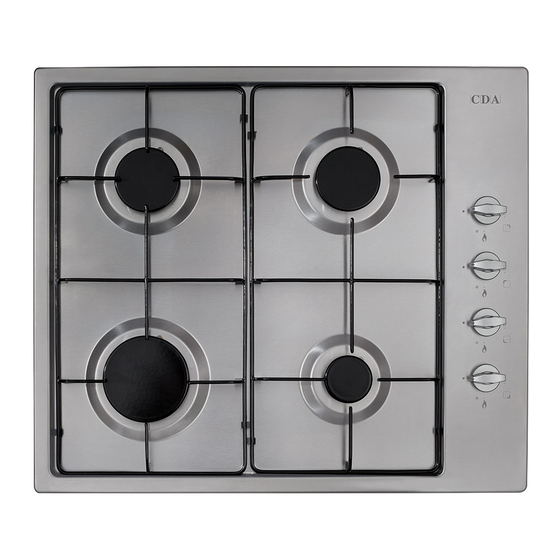
Using Your Hob Fig. 1 Gas burners: Gas flow to the burners is controlled by the control knobs (5, 6, 7 and 8 on the diagrams on pages 6 & 7). There are 3 positions shown on the control panel. Turning the control knob to the positions shown below achieves the following: Closed (OFF position) Maximum position: Provides fast boiling function... - Page 6 HG6150 Fig. 2 HG6250 & HG6350 Fig. 3...
- Page 7 Key to Figs 2 & 3 Gas burners: 1. Triple burner 3.8kW 2. Rapid burner 3.0kW 3. Semi-Rapid burner 1.85kW (HG6150) 1.75kW (HG6250 & HG6350) 4. Auxiliary burner 1.0kW Control panel: 5. Front left burner control knob 6. Back left burner control knob 7.
-
Page 8: Igniting The Burners
Igniting the Burners The hob is fitted with a flame failure device. Flame failure devices operate by shutting off the supply of gas to the burner in the event that the flame is extinguished accidentally. Fig. 4 To ignite the burners, follow these instructions: 1. - Page 9 Fig. 5 The table below shows the sizes of pan that should be used with each burner: Burner Size Minimum Pan Diameter (cm) Maximum Pan Diameter (cm) Auxiliary Semi-Rapid Rapid * Triple ** * HG6150 only ** HG6250 & HG6350 only...
- Page 10 Correct Use of the Optional Wok Pan Adaptor (HG6250 & HG6350 Only) The wok pan adaptor is a special stand that is designed to be fitted over the triple ring burner to give support to round bottomed woks. When using a wok, always place the wok pan adaptor in position over the pan support on the triple ring burner as shown in Fig.6.
-
Page 11: Care And Maintenance
Care and Maintenance As the hob has a stainless steel or enamel surface, you should use a nonabrasive cleaner. Any abrasive cleaner (including Cif) will scratch the surface and could erase the control panel markings. Stainless steel can be effectively cleaned by simply using a dilute solution of water and mild detergent and drying to a shine with a clean cloth. - Page 12 Burner Size Nominal Rating Simmer Rating LPG Flow Rate (lh (kW) (kW) Auxiliary 72.8 71.5 Semi-Rapid 1.85 (HG6150) 134.6 132.2 1.75 (HG6250/HG6350) Rapid 218.8 214.8 Triple / Wok Total rated gas input : 7.7kW (HG6150) 8.3kW (HG6250 & HG6350) Mains electrical voltage: 230 –...
-
Page 13: Mains Electricity Connection
Mains Electricity Connection THIS APPLIANCE MUST BE CONNECTED TO THE MAINS SUPPLY BY A COMPETENT PERSON, USING FIXED WIRING VIA A DOUBLE POLE SWITCHED FUSE SPUR OUTLET AND PROTECTED BY A 3A FUSE. DOUBLE POLE SWITCHED We recommend that the appliance is FUSE SPUR OUTLET connected by a qualified electrician, who is a member of the N.I.C.E.I.C. -
Page 14: Gas Supply Requirements
UK and Ireland. The installation must comply with the Gas Safety (installation and use) Regulations 1984. • The CDA Group Ltd is not legally able to provide any assistance in the installation of gas appliances except to Gas Safe registered installers. - Page 15 Ventilation All rooms require a window or equivalent (e.g. a door) which can be opened. Some rooms require a permanent vent in addition to a win- dow (see below). This unit must not be used in a room which is less than 5m .
-
Page 16: Natural Gas To Lpg Conversion
Natural Gas to LPG Conversion This hob can be converted from natural Required: gas to propane operation at a nominal • 7mm AF nut spinner • Replacement injectors inlet pressure of 37mbar, or butane • LPG identity plate operation at a nominal inlet pressure of 28/30mbar. - Page 17 LPG to Natural Gas Conversion Required: • 7mm AF nut spinner This hob can be converted from • Replacement injectors propane operation at a nominal • NG identity plate inlet pressure of 37mbar or butane operation at a nominal inlet pressure of 28/30mbar to natural gas at 20mbar.
-
Page 18: Fitting The Hob
Fitting the Hob Unpacking the hob: Take care not to lose or mishandle any parts. Fitting position of the hob: This appliance must be installed a minimum of 50mm from any back wall and a minimum of 150mm away from any adjacent vertical surfaces, e.g. - Page 19 withstanding temperatures 65°C above ambient or greater (typically 80-90°C). • If there is no oven to be built in below the hob it is recommended that, an isolation shelf should be fitted to protect the user from high temperatures. If the hob is to be installed above a working drawer, then a partition should be fitted to protect the contents and user from the heat generated during use.
- Page 20 2. Position the hob seal, as shown in the diagram below (Fig. 13), ensuring that the ends meet without overlapping. Do not use silicone type sealant. 3. Secure the hob to the worktop using the fixing brackets and screws supplied, as shown in the following diagram (Fig. 14). Remove any excess sealant after tightening the brackets.
- Page 21 NOTES:...
-
Page 22: Energy Efficiency Information
Energy Efficiency Information A) Measurement and calculation methods • The gas hob was CE approval according to the Gas Appliance Directives 2009/142/EC. • The energy efficiency of this gas hob was tested and measured according to EN 30-2-1-1998+A1-2003+A2-2005. • The semi-rapid burner and rapid burner were tested separately; the auxiliary burner is not required for test because its nominal heat input is less than 1.16kW. - Page 23 R: 56.56 Tr: 55.55 Tr: 54.88 Energy efficiency for the gas 56.37 56.03 55.8 Gas hob E & O E. All instructions, dimensions and illustrations are provided for guidance only. CDA reserve the right to change specifications without prior notice.
- Page 24 Group Ltd. • Harby Road • Langar • Nottinghamshire • NG13 9HY T : 01949 862 012 F : 01949 862 003 E : customer.care@cda.eu W : www.cda.eu T : 01949 862 012 F : 01949 862 003 E : customer.care@cda.eu W : www.cda.eu www.cda.eu...
Need help?
Do you have a question about the HG6150 and is the answer not in the manual?
Questions and answers