Advertisement
Quick Links
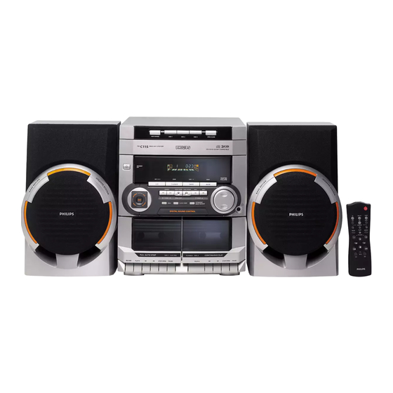
Mini System
Service
Service
Service
Service
Service
Service Manual
©
Copyright 2001 Philips Consumer Electronics B.V. Eindhoven, The Netherlands
All rights reserved. No part of this publication may be reproduced, stored in a retrieval system or
transmitted, in any form or by any means, electronic, mechanical, photocopying, or otherwise
without the prior permission of Philips.
Published by KC 0149 Service Audio
Version 1.0
Introduction of FW-C115/22
For Service documentation please refer to:
Service Manual:
FW-C100
Service Information:
A01-150
FW-C115/22 refers to FW-C100/22 except the following
adaptations:
1. Mechanical & Accessories
101
3139 118 17100
105
3139 118 17110
107
3139 118 17120
124
3139 118 17130
132
3139 118 17270
133
3139 118 17140
145
3139 118 17150
153
3139 118 17160
158
3139 118 17170
159
3139 118 17180
350
3139 118 79030
387
3139 115 21360
2. New 3CDC-LLC-MCD1 Module is attached.
Printed in The Netherlands
Subject to modification
3139 785 22520
3139 785 22930
Front Cabinet
Window CDC Control
Cover Tray CDC-LC
Window Display
Button Power On/Off
Button Set Source Select
Button DSC
Cover Control
Cover Cassette Left
Cover Cassette Right
Loudspeaker Box
Instruction For Use
FW-C115/
22
COMPACT
DIGITAL AUDIO
CLASS 1
LASER PRODUCT
GB
3139 785 30033
Advertisement

Related Manuals for Philips FW-C115/22


Summary of Contents for Philips FW-C115/22
- Page 1 LASER PRODUCT © Copyright 2001 Philips Consumer Electronics B.V. Eindhoven, The Netherlands All rights reserved. No part of this publication may be reproduced, stored in a retrieval system or transmitted, in any form or by any means, electronic, mechanical, photocopying, or otherwise without the prior permission of Philips.
- Page 2 10-1 3CDC-LLC-MCD1 (3 Disc Carousel Changer) Layout stage .3 TABLE OF CONTENTS Service Hints ..............10-2 Blockdiagram ..............10-5 Component Layout Main Board ........10-6 Circuit Diagram part1 ............10-7 Component Layout Main Board ........10-8 Circuit Diagram part2 ............10-9 Exploded View ..............10-10 Partslist ................10-12...
- Page 3 10-2 Service hints CAUTION CHARGED CAPACITORS ON THE SERVO BOARD MAY DAMAGE THE CD DRIVE ELECTRONICS WHEN CONNECTING A NEW CD MECHANISM. THAT´S WHY, BESIDES THE SAFETY MEASURES LIKE • SWITCH OFF POWER SUPPLY • ESD PROTECTION ADDITIONAL ACTIONS MUST BE TAKEN BY THE REPAIR TECHNICIAN. The following steps have to be done when replacing the CD mechanism: 1.
- Page 4 10-3 Service hints Dismantling of Tray 1. Open the tray. 2. Release 2x catch as shown in fig. 2 and Detail A 3. Pull tray out. Detail A fig.2 Assembling of Tray 1. Turn Cam (pos. 48) clockwise to end position.
- Page 5 10-4 Service Position...
- Page 6 10-5 10-5 BLOCK DIAGRAM 3CDC-LLC-MCD1 CD MECHANISM MAINBOARD MCD-1 DISC 7806 7802 TDA7073A TURNTABLE FOCB+ MOTOR FOCUS MOTOR FOCB- RADIAL RADB+ MOTOR RADB- 7805 1805 7807 TDA7073A SIGNAL PROCESSOR CD LEFT SLEDGEB+ SLEDGE CD10 MOTOR SAA7324 (SAA7325) SLEDGEB- Active low pass Analog Audio Filter TDA1308...
- Page 7 10-6 10-6 Mapping Copperside Componentside 2800 E3 3741 C4 3889 C2 1800 F2 2801 D4 3742 C4 3890 H2 1801 C5 3CDC-LLC Copperside view 3CDC-LLC Componentside view 2802 E4 3743 C3 3891 H2 1805 A2 2803 D4 3744 B4 3892 C2 1810 C2 2805 D4 3746 B3...
- Page 8 10-7 10-7 1800 F1 2804 D4 2811 A9 2818 B11 2826 G12 2838 D8 2851 B11 2888 C4 3702 D3 3721 D6 3792 F8 3800 D8 3807 B9 3819 D14 3828 G11 3839 H6 3846 F5 3863 G13 3895 G12 7803-B D5 MP713 C9 MP743 D2...
- Page 9 10-8 10-8 Mapping Copperside Componentside 2800 E3 3741 C4 3889 C2 1800 F2 2801 D4 3742 C4 3890 H2 1801 C5 3CDC-LLC Copperside view 3CDC-LLC Componentside view 2802 E4 3743 C3 3891 H2 1805 A2 2803 D4 3744 B4 3892 C2 1810 C2 2805 D4 3746 B3...
- Page 10 10-9 10-9 1805 E15 2830 C9 2858 A9 2865 C4 2877 F11 3705 G4 3713 G8 3730 G2 3741 A7 3751 C7 3851 D7 3865 A10 3874 C13 3880 E6 3886 E7 3898 F7 4876 D13 6875 F7 7805-B A8 7876 G3 MP726 D8 MP804 G14...
- Page 11 10-10 10-10 EXPLODED VIEW (3CDC-LC M ODULE 45 5x MECHANICAL PARTS Loader → this page ––––––––––––––––––––––––––––––––––––––––––––––––––––– 3103 304 66500 DRAWER 3140 114 29070 PRESSURE RING-MCD1 3140 111 21270 METAL RING-MCD1 3103 304 66560 SUPPORT 4822 529 10386 RUBBER DAMPER CD DRIVE, REAR 4822 529 10387 RUBBER DAMPER CD DRIVE, FRONT 3103 304 06970...
- Page 12 10-11 Drawer bottom view Drawer top view spare part non spare part 3CDC-LC Drawer assy 1999 09 13...
- Page 13 10-12 ELECTRICAL PARTSLIST 3CDC-LLC-MCD1 MODULE –––––––––––––––––––––––––––––––––––––––––––––––––––––––––––––––––––––––––––––––––––––––––––––––––––––––––––––––––– MISCELLANEOUS CAPACITORS ––––––––––––––––––––––––––––––––––––––––––––––––––––– ––––––––––––––––––––––––––––––––––––––––––––––––––––– 3103 309 05350 CD DRIVE MCD1B 2860 4822 124 11947 10µF 4822 361 10753 CAROUSEL MOTOR 2861 4822 124 11947 10µF 4822 361 10753 TRAY MOTOR 2862 © 4822 126 13883 220pF 1800 2422 025 17389...
- Page 14 10-13 ELECTRICAL PARTSLIST 3CDC-LLC-MCD1 MODULE –––––––––––––––––––––––––––––––––––––––––––––––––––––––––––––––––––––––––––––––––––––––––––––––––––––––––––––––––– RESISTORS RESISTORS ––––––––––––––––––––––––––––––––––––––––––––––––––––– ––––––––––––––––––––––––––––––––––––––––––––––––––––– 3801 © 4822 051 30103 10kΩ 0,06W 3880 © 4822 051 30392 3,9kΩ 0,06W 3802 © 4822 051 51831 18kΩ 0,1W 3881 © 4822 117 13632 100kΩ 0,06W 3803 © 4822 117 10833 10kΩ...
- Page 15 10-14 ELECTRICAL PARTSLIST 3CDC-LLC-MCD1 MODULE –––––––––––––––––––––––––––––––––––––––––––––––––––––––––––––––––––––––––––––––––––––––––––––––––––––––––––––––––– COILS TRANSISTORS ––––––––––––––––––––––––––––––––––––––––––––––––––––– ––––––––––––––––––––––––––––––––––––––––––––––––––––– 1810 4822 242 73557 CERAMIC RES. 8,46MHz 7802 © 5322 130 60123 BC807-40 7808 © 4822 130 60511 BC847B DIODES 7809 © 4822 130 60511 BC847B ––––––––––––––––––––––––––––––––––––––––––––––––––––– 7810 © 4822 130 60511 BC847B 6871 ©...
Need help?
Do you have a question about the FW-C115/22 and is the answer not in the manual?
Questions and answers