
Related Manuals for Digital Watchdog DWC-PTZ37X

Summary of Contents for Digital Watchdog DWC-PTZ37X
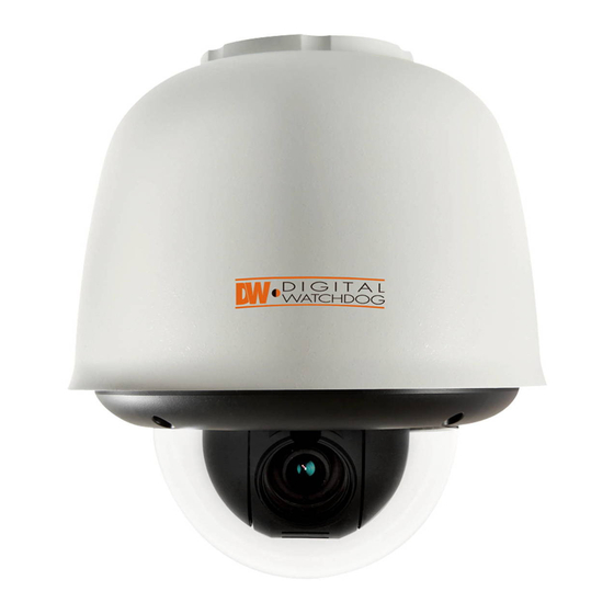
- Page 1 Analog PTZ Outdoor DWC-PTZ37X DWC-PTZ37XAL DWC-PTZ37XFM User’s Manual Before installing and using the camera, please read this manual carefully. Be sure to keep it handy for future reference.
-
Page 2: Safety Information
Safety Information CAUTION RISK OF ELECTRIC SHOCK. DO NOT OPEN CAUTION : TO REDUCE THE RISK OF ELECTRIC SHOCK, DO NOT REMOVE COVER (OR BACK). THERE ARE NO USER SERVICEABLE PARTS INSIDE. REFER SERVICING TO QUALIFIED SERVICE PERSONNEL. This symbol indicates that dangerous voltage This exclamation point symbol is intended to alert the consisting a risk of electric shock is present within user to the presence of important operating and... - Page 3 Safety Information CAUTION 1. Do not drop objects on the product or apply strong shock to it. Keep away from a location subject to excessive vibration or magnetic interference. 2. Do not install in a location subject to high temperature (over 50°C), low temperature (below -10°C), or high humidity.
- Page 4 Safety Instructions WARNING Read these instructions. Keep these instructions. Regard all warnings. Follow all instructions. Do not use this camera near water. Clean only with a dry cloth. Do not block any ventilation openings. Install in accordance with the manufacturer’s instructions. Do not install near any heat sources such as radiators, heat registers, or other apparatus (including ampli ers) that produce heat.
-
Page 5: Table Of Contents
Contents Safety Information Important Safety Instructions INTRODUCTION Features Product & Accessories Parts Name & Function INSTALLATION DIP Switch Setup Cabling Installation OSD MENU Check Points before Operation Reserved Presets Moving Around the OSD Menu Functions OSD Display of Main Screen General Rules of Key Operation for Menu OSD - ROOT MENU &... -
Page 6: Features
Features CAMERA SPECIFICATIONS PTZ (PAN/TILT/ZOOM) CONTROL • CCD Sensor: EX-View HAD • With RS485 communication, a maximum of 255 • Zoom Magnification: ×37 Optical, ×16 Digital Zoom cameras can be controlled at the same time. • Wide Dynamic Range • Auto, Pelco-D, Pelco-P, Samsung, Panasonic, Kalatel, •... -
Page 7: Product & Accessories
Joystick Controller DVR, Alarm Sensor, and Audio In and Out) 4. Drill 5. Screw Driver Mounting Accessory for the DWC-PTZ37X is sold separately with the camera’s wiring module. For wiring module in the dome, see DWC-PTZ37XFM and DWC-PTZ37XAL models. -
Page 8: Parts Name & Function
Part Name & Function Wall/Pendant Mount Bracket The Wall/Pendant Mount Bracket is used to secure the camera onto a wall or ceiling. It includes a built-in junction box. Depending on the camera’s model, the Junction box may include the inner box. The junction box accommodates the inner box. -
Page 9: Dip Switch Setup
DIP Switch Setup The DIP Switch is a control panel that is setup to a specific protocol so the camera can communicate with other devices, AUTO- Factory Default such as: Joystick Controller, DVR, PTZ Remote Controlling, Alarm Sensor, etc. Before installing the camera, you should set the DIP Switch to configure the Camera ID and Communication Protocol. - Page 10 DIP Switch Setup 2. Communication Baud Rate Setup 3. RS-485 Termination Resistor Select the appropriate Baud Rate with DIP switch combination. As factory Default, the camera’s Baud Rate is set to 2400 BPS. See page ____ for further information. 2400 BPS - The last Pin on the top line on the right, is used to turn ON/OFF RS-485 termination.
-
Page 11: Cabling
Cabling Inner Box Before you can begin mounting the PTZ37X, the cabling must be completed. RS-485 (Keyboard Controller/DVR) RS-485 Communication (DVR/Keyboard) 1. Connect RS-485 cable to terminal box matching the camera’s Inner box RS-485 Terminals. Connect the other end of the cable to a terminal box matching the DVR or keyboard controller RS-485 Terminals. - Page 12 Cabling Power Connection Requirements Please check the voltage and the current capacity of the rated power carefully. Input Current Rate Power Voltage Range Consumption AC 24V AC 19V ~ 29V 2.5A Power 1. Connect AC power adapter to the camera’s inner box. 2.
- Page 13 Cabling Video Output 1. Connect BNC coaxial cable to camera’s inner box. 2. Connect the other end of the BNC Coaxial cable to a DVR or Monitor. BNC Video Video Output...
- Page 14 Cabling Inner Box Alarm Output Alarm Input Alarm Output In 1 In 8 Alarm Input/Sensor Alarm Output Sensor Input The 4 alarm outputs are the relay contact type. To use alarm input, select the type of sensor you Therefore, you do not have to worry about the wish to use.
-
Page 15: Installation
Installation 1. Unscrew the top cover of the Mounting Box. 2. Remove the protective plastic to expose the four (4) screw holes. 3. Using the Mounting Box or the Mounting Template, locate on the wall/ ceiling the locations for the four (4) bolts. Note: the Anchor bolts included in with the camera kit are for concrete. - Page 16 Installation 5. Remove the PTZ mechanism from the upper housing. To detach camera mechanism, press down and hold both black handles on the camera mechanism. Pull them up to detach the camera. 6. Pass the cable connector from the inner box through the upper housing pipe. 7.
- Page 17 Installation 8. For outdoor installations, wind the weatherproof tape around the pipe of the upper housing. 9. Hook the safety wire to the safety hook on the upper housing and using the safety hanger, secure it to the mounting box/bracket. 10.
- Page 18 Installation 12. Snap camera back into the upper housing. Make sure the two black handles marked ‘A’ and ‘B’ correspond with the ‘A’ and ‘B’ markings on the sides of the upper housing. Note: Before snapping the camera back into the housing, make sure the cables are properly secured.
- Page 19 Installation Connect camera to power and make sure it is operating properly. 15. Camera will show Initializing Setup screen. Note: Please record the information on this screen, especially the Protocol (If set to Auto, it is probably Pelco-D), Baud Rate, and Camera’s Address. 16.
- Page 20 Installation 17. If no adjustments need to be made to the wiring, place the dome cover on the upper housing. 18. Secure dome to camera by fastening the screws on the dome in the order shown below. Note: This order of fastening the screws guarantees optimal sealing and protects the camera mechanism from the elements.
-
Page 21: Osd Menu
Check Points Before Operation 1. Before you can start controlling your PTZ37X camera, you need to make sure the Camera’s ID, Baud Rate and Protocol are setup in the DVR or Joystick Controller. 2. In the DVR, go to Menu --> Device --> PTZ 3. -
Page 22: Reserved Presets
Reserved Presets What is a Preset? A Preset is a unique command users can assign the camera. The PTZ37X supports up to 255 di erent Presets. Users can use 127 Presets to setup di erent positions for the camera Users can setup 1~128 Presets for di erent camera positions, except for preset 95. Preset 95 is reserved for starting the camera’s OSD menu. - Page 23 How to Move Around the OSD Menu Start OSD Menu Using the OSD menu, preset, pattern, scan, group, and alarm input function can be configured for each application. 1. Select Full Screen view on the selected PTZ camera 2. Right-Click the screen & Select ‘PTZ’ 3.
- Page 24 How to Move Around the OSD Menu 5. Using the mouse, click on the are of the screen labeled: UP: to scroll up the menu DOWN: to scroll down the menu Left: Vertically move from one edit tab to the one to its left RIGHT: Vertically move from one edit tab to the one to its right.
- Page 25 How to Move Around the OSD Menu To move to a sub-menu 1. Click on the top/bottom of the screen to select the desired sub-menu from the list. 2. Once you have selected the sub-menu you want to enter, scroll the mouse’s wheel forward To exit a sub-menu 3.
- Page 26 How to Move Around the OSD Menu To move between input tabs 1. Using previous instructions, select the sub-menu and category you wish to modify 2. Scroll the mouse’s wheel forward to enter edit mode 3. The system will show it is in edit mode by highlighting the first tab...
- Page 27 How to Move Around the OSD Menu 4. Click on the top/bottom of the screen to increase/reduce the values of the data you are modifying 5. When you have completed modifying the first data tab, click on the left side of the screen to move to the next data tab. 6.
-
Page 28: Functions
Functions Preset Group Maximum 127 positions can be stored as preset The group function allows you to run sequence of positions. The preset number can be assigned from presets, pattern, and/or scans. 1 to 128, but 95 is reserved for starting OSD menu. See section “ROOT MENU >... -
Page 29: Osd Display Of Main Screen
OSD Display of Main Screen PRESET LABEL PATTERN 1 Preset Label Action Title CAMERA ID_TOP Camera ID_Top CAMERA ID_TOP CAMERA ID_BOT Alarm I/O Information Camera ID_Bottom CAMERA ID_BOT Compass Direction O 1234 23/MAR/2009 Date / Time I 12345678 24 00 00 Zoom Magnification 359/180/x100/SE CAM 1... -
Page 30: General Rules Of Key Operation For Menu
General Rules of Key Operation for Menu The menu items surrounded with < > always has ROOT MENU a sub menu. - - - - - - - - - - - - - - - - - - - - - - - - - - - <SYSTEM INFORMATION>... - Page 31 OSD - ROOT MENU & SYSTEM INFORMATION ROOT MENU ROOT MENU - - - - - - - - - - - - - - - - - - - - - - - - - - - <SYSTEM INFORAMTION> <SYSTEM INFORMATION>...
-
Page 32: Osd - Display Setup > Camera Id
OSD - DISPLAY SETUP > CAMERA ID DISPLAY SETUP DISPLAY SETUP This menu defines what is displayed on the OSD of the - - - - - - - - - - - - - - - - - - - - - - - - - - - ADDRESS main screen. -
Page 33: Osd - Display Setup > Privacy Zone
OSD - DISPLAY SETUP > PRIVACY ZONE DISPLAY SETUP DISPLAY SETUP See the previous page. - - - - - - - - - - - - - - - - - - - - - - - - - - - ADDRESS CAMERA ID EDIT MASK - Move to Target Position... - Page 34 OSD - DISPLAY SETUP > PRIVACY ZONE PRIVACY ZONE - STYLE > COLOR PRIVACY ZONE Set the color of the mask. - - - - - - - - - - - - - - - - - - - - - - - - - - - MASK NO.
-
Page 35: Osd - Motion Setup
OSD - MOTION SETUP MOTION SETUP MOTION SETUP Setup the general functions of pan/tilt motions. - - - - - - - - - - - - - - - - - - - - - - - - - - - PRESET LOCK PWR UP ACTION PRESET LOCK... - Page 36 OSD - MOTION SETUP ALARM INPUT SETUP MOTION SETUP If an external sensor is activated, camera will move to - - - - - - - - - - - - - - - - - - - - - - - - - - - PRESET LOCK the corresponding action.
-
Page 37: Osd - Function Setup > Preset Setup
OSD - FUNCTION SETUP > PRESET SETUP FUNCTION SETUP FUNCTION SETUP Configure 5 special functions with this menu. - - - - - - - - - - - - - - - - - - - - - - - - - - - <PRESET SETUP>... - Page 38 OSD - FUNCTION SETUP > PRESET SETUP LABEL PRESET SETUP Edits the label to show on monitor when camera arrives at - - - - - - - - - - - - - - - - - - - - - - - - - - - PRESET NO.
-
Page 39: Osd - Function Setup > Scan Setup
OSD - FUNCTION SETUP > SCAN SETUP SCAN SETUP FUNCTION SETUP By using the scan function, you can make the camera to move - - - - - - - - - - - - - - - - - - - - - - - - - - - <PRESET SETUP>... -
Page 40: Osd - Function Setup > Pattern Setup
OSD - FUNCTION SETUP > PATTERN SETUP PATTERN SETUP FUNCTION SETUP Pattern function is when a camera memorizes the path (mostly - - - - - - - - - - - - - - - - - - - - - - - - - - - <PRESET SETUP>... -
Page 41: Osd - Function Setup > Group Setup
OSD - FUNCTION SETUP > GROUP SETUP GROUP SETUP FUNCTION SETUP The group function allows you to run sequence of presets, pattern, - - - - - - - - - - - - - - - - - - - - - - - - - - - <PRESET SETUP>... - Page 42 OSD - FUNCTION SETUP > GROUP SETUP EDIT GROUP - Selects Function Sequence EDIT GROUP When you finish setting up an ACTION, press Near or Enter key - - - - - - - - - - - - - - - - - - - - - - - - - - - NO.
-
Page 43: Osd - Function Setup > Schedule Setup
OSD - FUNCTION SETUP > SCHEDULE SETUP SCHEDULE SETUP SCREEN FUNCTION SETUP The schedule function allows running an appropriate function - - - - - - - - - - - - - - - - - - - - - - - - - - - <PRESET SETUP>... - Page 44 OSD - FUNCTION SETUP > SCHEDULE SETUP SCHEDULE SETUP The second rule means camera will move to preset 12 at 7:00 - - - - - - - - - - - - - - - - - - - - - - - - - - - MASTER ENABLE every Wednesday.
-
Page 45: Osd - Camera Setup > Wb Setup
OSD - CAMERA SETUP > WB SETUP ZOOM CAMERA SETUP ZOOM CAMERA SETUP Basically the camera setup is same as x27, x33, x36, x37 except - - - - - - - - - - - - - - - - - - - - - - - - - - - SEMIAUTO FOCUS MODE for “DIS MODE,”... -
Page 46: Osd - Camera Setup > Ae Setup
OSD - CAMERA SETUP > AE SETUP AE SETUP AE SETUP - - - - - - - - - - - - - - - - - - - - - - - - - - - IRIS ALC / MANUAL IRIS <ALC>... - Page 47 OSD - CAMERA SETUP > AE SETUP DAY/NIGHT AE SETUP The camera automatically detects the change by the - - - - - - - - - - - - - - - - - - - - - - - - - - - IRIS <ALC>...
-
Page 48: Osd - Camera Setup > Special
OSD - CAMERA SETUP > SPECIAL ZOOM CAMERA SETUP ZOOM CAMERA SETUP - - - - - - - - - - - - - - - - - - - - - - - - - - - FOCUS MODE SEMIAUTO DIGITAL ZOOM IMAGE FLIP... - Page 49 OSD - SYTEM SETUP SYSTEM SETUP SYSTEM SETUP - - - - - - - - - - - - - - - - - - - - - - - - - - - <DATE/TIME SETUP> <DATE/TIME SETUP> <RELAY TYPE> Opens DATE/TIME SETUP menu.
- Page 50 OSD - SYTEM SETUP SET HOME POSITION SET HOME POSOTION Home position means the origin of pan angle calculation. - - - - - - - - - - - - - - - - - - - - - - - - - - - The value of pan angle displayed on the screen is based on this home position.
- Page 51 OSD - SYSTEM INITIALIZE Initial Configuration Table SYSTEM INITIALIZE Address - - - - - - - - - - - - - - - - - - - - - - - - - - - CLEAR ALL DATA Camera ID CLR DISPLAY SET CLR CAMERA SET...
-
Page 52: Dimension
Speci cations - Dimension Unit: mm 38.1 (1.5”) 101.5... - Page 53 Speci cations - Speci cation_x37 Signal Format NTSC Image Device 1/4” ExView-HAD PS CCD Total Pixel 410K pixels [811 (H) x 508 (V)] 470K pixels [795 (H) x 596 (V)] E ective Pixel 380K pixels [768 (H) x 494 (V)] 440K pixels [752 (H) x 582 (V)] H.
-
Page 54: Troubleshooting
Troubleshooting Before sending your camera for repair, check the following or contact our technical support specialists. PROBLEM SOLUTION Notimage appears on the screen. Check that the power cable is connected properly to the camera and that it meets the camera’s power requirements. Check that the line connection between the camera and monitor is fixed properly.Check that you have properly connected BNC cable to the camera. - Page 55 WARRANTY INFORMATION Digital Watchdog (referred to as “the Warrantor”) warrants the Digital Watchdog Camera against defects in materials or workmanship as follows: LABOR : For the initial two (2) years and one (1) year on PTZ Zoom Module from the original purchase date, if the camera is determined to be defective, the Warrantor will repair or replace the unit with a new or refurbished product at its option at no charge.
- Page 56 Appendix I Setting the Camera’s ID using the DIP Switch Use the following table as a quick reference to the Pin values and positions required for each individual ID number. The unique Pin combination equals a different ID you can use to define you camera in a situatoin where you want to control multiple cameras.
- Page 57 Appendix I Setting the Camera’s ID using the DIP Switch Pin Value...
- Page 58 Appendix I Setting the Camera’s ID using the DIP Switch Pin Value...
- Page 59 Appendix I Setting the Camera’s ID using the DIP Switch Pin Value...
- Page 60 Appendix I Setting the Camera’s ID using the DIP Switch Pin Value...
- Page 61 Appendix I Setting the Camera’s ID using the DIP Switch Pin Value...
- Page 62 5436 W Crenshaw St. Tampa, FL 33634 Tel : 866-446-3595 / 813-888-9555 Fax : 813-888-9262 www.Digital-Watchdog.com technicalsupport@dwcc.tv Technical Support Hours : Monday-Friday 8:30am to 8:00pm Eastern Time Correct Disposal of This Product (Waste Electrical & Electronic Equipment) (Applicable in the European Union and other European countries with separate collection systems) This marking on the product, accessories or literature indicates that the product and its electronic accessories (e.g.
Need help?
Do you have a question about the DWC-PTZ37X and is the answer not in the manual?
Questions and answers