Table of Contents
Advertisement
Quick Links
WHITE-RODGERS
Operator: Save these instructions for future use!
FAILURE TO READ AND FOLLOW ALL INSTRUCTIONS CAREFULLY
BEFORE INSTALLING OR OPERATING THIS CONTROL COULD CAUSE
PERSONAL INJURY AND/OR PROPERTY DAMAGE.
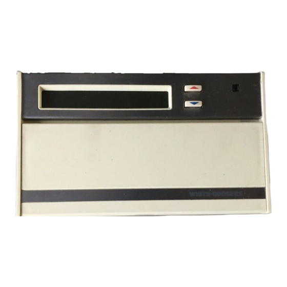
This wall-mounted, low voltage thermostat maintains
room temperature by controlling the operation of heating
and cooling systems. The user may program up to four
time/temperature settings per 24 hour period. The ther-
mostat stores independent heating and cooling programs
for 5-day (weekday) and 2-day (weekend) periods. The
thermostat will store both heating and cooling programs
simultaneously. Three "AA" Energizer
maintain the stored program for approximately one year,
if incoming power should fail. If power failure is extensive
and the program is lost, after power restoration, the
thermostat will automatically maintain a factory
preprogrammed heating temperature of 64°F or a cooling
temperature of 82°F.
If in doubt about whether your wiring is millivolt, line, or low
voltage, have it inspected by a qualified heating and air
conditioning contractor, electrician, or someone familiar
with basic electricity and wiring.
CONTENTS
Description ......................................................... 1
Precautions ........................................................ 1
Specifications ..................................................... 2
Installation .......................................................... 2
Operation ........................................................... 6
WHITE-RODGERS DIVISION
EMERSON ELECTRIC CO.
9797 REAVIS ROAD
ST. LOUIS, MISSOURI 63123
R
5-Day/2-Day Electronic Digital Thermostat
INSTALLATION INSTRUCTIONS
®
batteries will
Do not exceed the specification ratings.
All wiring must conform to local and national electrical
codes and ordinances.
This control is a precision instrument, and should be
handled carefully. Rough handling or distorting compo-
nents could cause the control to malfunction.
To prevent electrical shock and/or equipment
damage, disconnect electric power to system, at
main fuse or circuit breaker box, until installation
is complete.
Do not use on circuits exceeding specified volt-
age. Higher voltage will damage control and
could cause shock or fire hazard.
Do not short out terminals on gas valve or pri-
mary control to test. Short or incorrect wiring will
burn out thermostat and could cause personal
injury and/or property damage.
Printed in U.S.A.
1F90W-71
DESCRIPTION
W H I T
E - R O
D G E R
S
PRECAUTIONS
CAUTION
!
WARNING
!
PART NO. 37-5087A
9139
Advertisement
Table of Contents

Subscribe to Our Youtube Channel
Related Manuals for White Rodgers 1F90W-71

Summary of Contents for White Rodgers 1F90W-71
-
Page 1: Table Of Contents
1F90W-71 WHITE-RODGERS 5-Day/2-Day Electronic Digital Thermostat INSTALLATION INSTRUCTIONS Operator: Save these instructions for future use! FAILURE TO READ AND FOLLOW ALL INSTRUCTIONS CAREFULLY BEFORE INSTALLING OR OPERATING THIS CONTROL COULD CAUSE PERSONAL INJURY AND/OR PROPERTY DAMAGE. DESCRIPTION This wall-mounted, low voltage thermostat maintains room temperature by controlling the operation of heating and cooling systems. -
Page 2: Specifications
SPECIFICATIONS ELECTRICAL DATA Shipping Temperature Range: Electrical Rating: -40°F to 150°F 17 to 30vAC 50/60 Hz. 0.05 to 1.5 Amps APPLICATIONS 1.5 Amps Maximum Total Load (All terminals For use with: combined) • Standard heat/cool or heat-only systems • Three-wire zone valve systems Anticipation: •... -
Page 3: Replacement Installation
REPLACEMENT INSTALLATION TABLE 1. OLD THERMOSTAT IDENTIFICATION OLD THERMOSTAT THERMOSTAT REMOVE OLD THERMOSTAT TERMINAL IDENTIFICATION TYPE Type 1. Shut off electricity at the main fuse box until installa- tion is complete. Verify power is off with a voltmeter. Type 2. Remove the front cover of the old thermostat. With wires still attached, remove wall plate from the wall. - Page 4 NOTE CAUTION All wiring diagrams are for typical systems only. Refer to To prevent electrical shock and/or equipment equipment manufacturers' instructions for specific sys- damage, disconnect electrical power at the main tem wiring information. fuse box or circuit breaker until installation is complete.
- Page 5 From millivolt system THERMOSTAT SYSTEM Millivolt System From millivolt system Thermostat Terminal Connections Figure 8. Typical Wiring Diagram for Millivolt Systems From millivolt system From 24vAC transformer THERMOSTAT SYSTEM Millivolt Cooling System System Relay 24vAC 120vAC Neutral TRANSFORMER From fan relay From cooling system Thermostat Terminal Connections Figure 9.
-
Page 6: Attach Thermostat To Subbase
pin connectors and the plastic snaps lock into place (see ATTACH THERMOSTAT TO SUBBASE Fig. 12). Be gentle when attaching thermostat. If the thermostat does not seem to be attaching to the subbase IT IS RECOMMENDED THAT YOU SET OPTION easily, make sure that the connector pins and plastic SWITCHES TO DESIRED POSITION BEFORE ATTACH- snaps are properly aligned, and that excess wire is... -
Page 7: Electric Heat Systems
2. Manual Changeover (Heating/Cooling Systems 2. Press until FAN ON is displayed. The blower Only) – AUTO should begin to operate (this will work only on sys- Switch #1 OFF tems with a G terminal). Switch #2 OFF Switch #3 (see step B5) On three-wire heat only systems, or on four-wire heat/ cool systems, if the thermostat display is operating 3. -
Page 8: Cooling System
COOLING SYSTEM If the thermostat display is operating properly, but the cooling system does not operate when the above steps are performed, the red jumper wire (provided CAUTION with thermostat) may not be properly installed be- tween the RH and RC terminals. Disconnect electri- To prevent compressor and/or property damage, cal power to system and properly install the jumper if power to the compressor has been off or...
Need help?
Do you have a question about the 1F90W-71 and is the answer not in the manual?
Questions and answers