Table of Contents
Advertisement
Advertisement
Table of Contents

Related Manuals for POFUNG P15UV


Summary of Contents for POFUNG P15UV
- Page 2 PREFACE Thank you for purchasing P15UV Two Way Radio, It is a multitask GMRS transceiver. Combining the latest technology in radio communication along with a sturdy mechanical frame, P15UV is the ideal and effective solution for the professionals who need to stay in touch with the working team (in construction sites, buildings, shows, trade fairs or hotels) or for leisure users that just want to keep up with friends and family.
-
Page 3: Table Of Contents
Table of Contents 1. GETTING STARTED 1.1 Regulations and Safety Warnings 1.2 Content of the packaging 1.3 Main features 1.4 Maintenance 2. BATTERY INFORMATION 2.1 Charging the Battery Pack 2.2 Charger Supplied 2.3 Use Caution with the Li-ion Battery 2.4 How to Charge 2.5 LED Indicator 2.6 How to Store the Battery 2.7 Using the Type-C USB Charger... - Page 4 5.1 Power on the radio 5.2 Adjusting the volume 5.3 Channel selection 5.4 Making a call 5.5 Frequency (VFO) mode 5.6 Channel (MR) mode 6. ADVANCED FEATURES 6.1 Frequency scanning 6.2 Channel scanning 6.3 CTCSS scanning 6.4 DCS scanning 6.5 Cursor Conversion (A/B) 6.7 Keypad lock 6.8 FM Radio (FM) 6.9 TX 1000Hz, 1450Hz, 1750Hz, 2100Hz repeaters tone...
-
Page 5: Getting Started
1. GETTING STARTED 1.1 Regulations and Safety Warnings ■ FCC COMPLIANCE This device complies with Part 15 of the FCC Rules. Operation is subject to the condition that this device does not cause harmful interference. Our radio generators RF electromagnetic energy during transmit mode. This radio is designed for and classified as“General Population”,meaning it must be used only during the course of employment by individuals aware of the hazards, and the ways To Minimize Such hazards. - Page 6 0 cm. Do not use this device when antenna shows obvious damages. This product is compliance to FCC RF Exposure requirements and refers to FCC website https://apps.fcc.gov/oetcf/eas/reports/GenericSearch.cfm search for FCC ID: 2AJGM-P15UV to gain further information include SAR Values. ■...
- Page 7 • Never open your radio’s case. • Never change or replace anything in your radio except the battery. • Any attempt to change frequencies or output power of the radio invalidates the approval RF Exposure Information WARNING! Read this information before using the radio. In August 1996 the Federal Communications Commission (FCC) of the United States with its action in Report and Order FCC 96-326 adopted an updated safety standard for human exposure to radio frequency electromagnetic energy emitted by FCC regulated transmitters.
- Page 8 Replacement or substitution of transistors, regular diodes or other parts of a unique nature, with parts other than those recommended by Pofung may cause a violation of the technical regulations of part 95 of the FCC rules, or violation of type acceptance requirements of part 2 of the rules.
-
Page 9: Content Of The Packaging
1.2 Content of the packaging • 1 P15UV transceiver • 1 Li-Ion battery pack 1500mAh 7.4V • 1 Fast desktop charger • 1 Wall adaptor • 1 Belt clip If any item is missing, please verify with your dealer. 1.3 Main features •... -
Page 10: Maintenance
About Range Your P15UV Series radios are designed to give you maximum range under optimum conditions. • Maximum Range: Little to No sight Obstruction. • Medium Range: Partial Obstruction to line of sight. • Short Range: Major Obstruction to Ling of Sight. -
Page 11: Battery Information
If this is the case, replace the battery pack. 2.2 Charger Supplied Please use the specified charger provided by POFUNG. Other models may cause explosion and personal injury. After installing the battery pack, and if the radio displays low battery with a voice prompt, please charge the battery. -
Page 12: How To Charge
f. Do not charge the battery or the radio if it is damp. Dry it before charging to avoid damage. WARNING! When keys, ornamental chain or other electric metals contact the battery terminal, the battery may become damage or injure a human. If the battery terminals are short circuited it will generate a lot of heat. Take care when carrying and using the battery. -
Page 13: How To Store The Battery
2.6 How to Store the Battery a. If the battery needs to be stored, keep it in status of 80% discharged. b. It should be kept in low temperature and dry environment. c. Keep it away from hot places and direct sunlight. »... -
Page 14: Installation Of Accessories
3. INSTALLATION OF ACCESSORIES Before the radio is ready for use we need to attach the battery pack, as well as charge the battery. 3.1 Installing the belt clip a. At the back of the radio there are two parallel screws mounted above the battery, remove these and thread them through the holes on the belt clip as you screw them back into the radio body. -
Page 15: Radio Overview
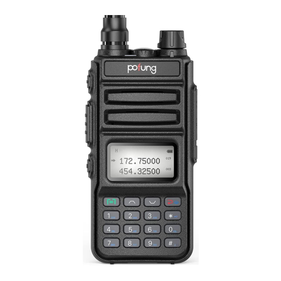
4. RADIO OVERVIEW... - Page 16 1. Antenna 2. Power Switch / Volume control: Rotate to switch on/off the radio and adjust the volume 3. Speaker 4. Microphone 5. LCD display MENU) key: enter the MENU functions and confirms the selection. In standby mode, press and hold the key to switch between frequency mode an MENU d channel mode.
-
Page 17: Main Controls And Parts Of The Radio
4.2 Main controls and parts of the radio LCD Display 1. Received signal strength. 2. power. 3. Appears when DTMFST (DT-ST / DT + ANI / ANI-ST) is activated. 4. These symbols show that you set a DCS or CTCSS code in tx or rx. In tx mode it appears while you are transmitting, while in rx mode it is shown also in stand-by condition. -
Page 18: Status Indications
13/17. Depending on the setting, it will show the frequency in use, the channel name, the menu setting, etc 14/15. Indicates the VFO in use and the current menu or function setting. This icon is displayed close to the band in use or to the menu settings. - Page 19 or UHF) in the main or secondary display. When listening to broadcast FM, the key switches between 65-75 MHz and 76-108 MHz band. Press and hold this key for 5 seconds to switch between GMRS communication and NoAA weather reception mode. Numeric keypad •...
-
Page 20: Basic Operations
5. BASIC OPERATIONS 5.1 Power on the radio Turning the unit on • To turn the unit on, simply rotate the volume/power knob clockwise until you hear a "click". If your radio powers on correctly there should be an audible double beep after about one second and the display will show a message or flash the LCD depending on settings for about one second. -
Page 21: Making A Call
5.4 Making a call NOTE: Press the key to switch the main channel to the other channel if there are 2 channels shown on the display. In standby mode, press and hold the key to switch between frequency (VFO) mode and channel (MR) mode. •... -
Page 22: Channel (Mr) Mode
WARNING! Just because you can program in a channel does not mean you're automatically authorized to use that frequency. Transmitting on frequencies you're not authorized to operate on is illegal, and in most jurisdictions a serious offence. However, it is legal in most jurisdictions to listen. Contact your local regulatory body for further information on what laws, rules and regulations apply to your area. -
Page 23: Channel Scanning
Directly press key to move the cursor up and down. Then, you can modify or confirm the parameters indicated by the cursor. Important1: P15UV has a dual-frequency display function. In frequency mode, you will see on the display two different... -
Page 24: Keypad Lock
Memory channels are an easy way to store commonly used frequencies so that they can easily be retrieved at a later date. The POFUNG P15UV features 220 memory channels that each can hold: Receive frequencies, group signaling information, bandwidth, ANI/ PTT-ID settings and a six character alphanumeric identifier or channel name... - Page 25 Frequency Mode vs. Channel Mode In standby mode, press and hold the key to switch between frequency (VFO) mode and channel (MR) mode. These two modes have different functions and are often confused. Frequency Mode (VFO) : Used for a temporary frequency assignment, such as a test frequency or quick field programming if permitted.
-
Page 26: Built-In Led Flashlight
B. Press and hold the key to set the radio to VFO mode, and the VFO icon is displayed on the right. [1][8] Enter the scan range menu D. Enter [4][3][0][4][3][5] Enter the scan frequency range E. Press and hold the key to start frequency Frequency required for scanning scan, 432.55000 frequency points start to scan. -
Page 27: Working The Menu System
NOAA weather scan. The radio will stop scanning and the display will show the current WX Band channel setting. To turn the NOAA weather receiver off, press the key. Note: NOAA weather radio stations are assigned to cover specific areas and service may be limited. Please check with your local weather office for frequency and details or visit www.weather.gov/nwr in the US to view the appropriate transmitter for your area. -
Page 28: Functions And Operations
Thanks to this function you can adjust the squelch in 10 different levels: • Level 0: opened squelch. With this setting, P15UV will detect all signals, also the weakest ones, but will also receive the background noise or undesired signals. - Page 29 You have 5 selections available: Off/ Mode 1/ Mode 2/ Mode 3/ Mode 4. For example: Mode 1= 1s’ working and 1s’ battery saving. Mode 2= 1s’ working and 2s’ battery is saving. NOTE: The higher the number the longer the battery lasts. The higher number increases the RX sleep cycle, but you may miss the first few syllables before the RX opens (4) VOX Function (Vox Level ) - MENU No.3 This function allows hands-free conversations: just speak in the direction of the microphone and the communication will be...
- Page 30 You can choose amongst: • Off: • D023N-D754N (Normal DCS), D023I-D754I (Inverse DCS) Note: In P15UV there are 208 groups of normal and inverse DCS codes. This function cannot be amended in channel mode. (11) Receiving CTCSS (Rx CTCSS) - MENU No.10 As DCS codes, the CTCSS codes can be added to the channels for creating new private channels.
- Page 31 (15) ANI-ID (ANI-ID) - MENU No.14 With this function you can set your ID-code. It can be programmed by the proper programming software. You can edit up to 5 digits. (16) DTMFST (DTMFST) - MENU No.15 Determines when DTMF Side Tones can be heard from the transceiver speaker. You can choose amongst four options: •...
- Page 32 Thanks to this function, P15UV can SCAN in frequency or channel mode. You can choose amongst three options: • Time-operated SCAN Whenever a signal is detected, the radio will suspend the SCAN for 5 seconds, and then will continue to SCAN even if the signal is still present.
- Page 33 • Frequency: Frequency + channel No. • Name: Channel name Note: Channel name mode must be set by the programming software. Up to three numbers or characters can be edited. (24) Busy Channel Lock (Busy Lock) - MENU No. 23 When this function is on, it may prevent other radios’...
- Page 34 (33) Squelch tail elimination (TAIL) - Menu No. 32 This function is used eliminate squelch tail noise between POFUNG handhelds that are communicating directly (no repeater). Reception of a 55 Hz or 134.4 Hz tone burst mutes the audio long enough to prevent hearing any squelch tail noise.
- Page 35 (34) Squelch tail elimination of repeater (RP-STE) - Menu No. 33 This function is used when the radio operates through a repeater; when the PTT is released, the repeater will emit the end transmission tone to confirm it is working. Available settings: Off, 1,2,3,4,5,….10 to set the delay time.
- Page 36 (39) Language selection (Language) - Menu No. 38 With this function, you can select the language of the LCD display and operation prompt. (40) Frequency hopping system (Hopping RX) - MENU No. 39 With this function, you can activate the frequency hopping system, improve the anti-interference ability of the radio, and reduce the risk of being monitored.
-
Page 37: On-Line Service And Support
Warning Notes every effort has been made to ensure that the information in this document is complete, accurate, and up to-date. POFUNG Radio assumes no responsibility for the results of errors beyond its control. The manufacturer of this equipment also cannot guarantee that changes in the equipment made by non-authorized users will not affect the... -
Page 38: Appendix A. - Trouble Shooting Guide
Appendix A. – Trouble shooting guide Phenomena Analysis Solution The battery may be installed improperly. Remove and reattach the battery. The battery power may run out. Recharge or replace the battery. You cannot turn on the radio. The battery may suffer from poor contact caused Clean the battery contacts or replace the by dirty or damaged battery contacts. -
Page 39: Appendix B. - Technical Specifications
Appendix B. - Technical Specifications General Frequency Range GRSM(RX & TX) 136-174 & 400-512MHz(RX) Memory Channel 30 GMRS+11 NoAA weather Channels+220 Scanner Operation Voltage DC 7.4 V ±10% Battery Capacity 1500mAh (Li-Ion) Frequency Stability ±2.5ppm Operating Temperature -20℃ to +50℃ Mode of Operation Simplex Antenna Impedance... -
Page 40: Appendix C. - Shortcut Menu Operations
Appendix C. - Shortcut Menu operations MENU Name Enter item LCD display Selectable (Full Name) 0-9 Levels Squelch - Squelch MENU+0 0:Lowest Level 9:Highest Step –Step 2.5K/5.0K/6.25K/10.0K MENU+1 12.5K/20.0K/25.0K/50.0K Frequency Power Save - OFF: MENU+3 1, 2, 3, 4 Battery Saving Vox Level - VOX MENU+3 GMRS Version not support... - Page 41 D.Wait – Dual MENU+6 *Monitor [A] and [B] at the same time. The display Watch Operation with the most recent activity ([A] or [B]) becomes the selected display. Beep- Keypad MENU+7 Beep *Allows audible confirmation of a key press. 15,30…600S *This feature provides a safety switch that limits transmission time to a programmed value.
- Page 42 D023N…D754N; D023I …D754I Tx DCS MENU+11 *Transmits a specific low-level digital signal to -Transmitter DCS unlock the squelch of a distant receiver (usually a repeater). 67.0HZ…254.1HZ Tx CTCSS - MENU+12 *Transmits a specific and continuous sub audible Transmitter CTCSS signal to unlock the squelch of a distant receiver (usually a repeater).
- Page 43 ON: the current channel is added to the scan, the Scan Add-Scan MENU+17 scan current channel channel add OFF: Do not scan the current channel. 136-174 & 400-512MHz *Ex. 144 148 input and scan range is Scan Ran- Scan MENU+18 144.0000-148.0000 Frequency Range * Scanning frequency range, valid in VFO mode.
- Page 44 Busy Lock – Busy *Disables the [PTT] button on a channel that is MENU+23 already in use. The transceiver will sound a beep Channel Lock-out tone and will not transmit if the [PTT] button is pressed when a channel is already in use. AUTO LK –Automatic MENU+24...
- Page 45 *Automatic stop after receiving the DCS signal *This function is used eliminate squelch tail noise TAIL - Squelch Tail MENU+32 between POFUNG handhelds that are Elimination communicating directly (no repeater). Reception of a 55 Hz or 134.4 Hz tone burst mutes the audio long enough to prevent hearing any squelch tail noise.
- Page 46 1000Hz/1450Hz/1750Hz/2100Hz R-TONE–Repeater MENU+36 *To send out a repeater tone; You hold down the Tone [PTT] + [LAMP/MONI] key. Logo: Performs an LCD screen test at power-on Msg : Displays a 2-line power on message OPNSET -Power MENU+37 Voltage: On Message *Controls the behavior of the display when the transceiver is turned on.
- Page 47 Appendix D. - GMRS Frequency Chart (MHz) Type of Power Type of Power CH.No CH.Freq. CH.No CH.Freq. Radio Output Radio Output 462.5625 GMRS High 462.5750 GMRS High 462.5875 GMRS High 462.6000 GMRS High 462.6125 GMRS High 462.6250 GMRS High 462.6375 GMRS High 462.6500...
- Page 48 Appendix E. - DCS Table DCS CODE LIST Number Code Number Code Number Code Number Code Number Code D023N D025N D026N D031N D032N D036N D043N D047N D051N D053N D054N D065N D071N D072N D073N D074N D114N D115N D116N D122N D125N D131N D132N D134N D143N...
- Page 49 D731N D732N D734N D743N D754N D023I D025I D026I D031I D032I D036I D043I D047I D051I D053I D054I D065I D071I D072I D073I D074I D114I D115I D116I D122I D125I D131I D132I D134I D143I D145I D152I D155I D156I D162I D165I D172I D174I D205I D212I D223I D225I D226I...
- Page 50 Appendix F. - CTCSS Table CTCSS CHART (Hz) Number Frequency Number Frequency Number Frequency Number Frequency Number Frequency 67.0 69.3 71.9 74.4 77.0 79.7 82.5 85.4 88.5 91.5 94.8 97.4 103.5 107.2 110.9 114.8 118.8 123.0 127.3 131.8 136.5 141.3 146.2 151.4 156.7...
- Page 51 Disclaimer The Company endeavors to achieve the accuracy and completeness of this manual, but no warranty of accuracy or reliability is given. All the specifications and designs are subject to change without notice due to continuous technological development. No part of this manual may be copied, modified, translated, or distributed in any manner without the prior written consent of the Company.
Need help?
Do you have a question about the P15UV and is the answer not in the manual?
Questions and answers