Advertisement
GE Appliances
Part Install Instructions
WH12X10457, WH12X10544, WH12X10520,
WH12X20814, WH12X23454, WH12X23462,
WH12X24234, WH12X25894, WH12X25895 Controls
!
IMPORTANT SAFETY NOTICE
The information in this part instruction is intended for use by
individuals possessing adequate backgrounds of electrical,
electronic and mechanical experience. Any attempt to repair a
major appliance may result in personal injury and property
damage. The manufacturer or seller cannot be responsible for the
interpretation of this information, nor can it assume any liability in
connection with its use.
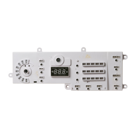
Parts Included:
•
Control Board
Instruction Sheet
•
Overview – Procedure for programming new control boards with all
LED's flashing.
When replacing the User Interface (UI) control, the washer will not function properly until the replacement
control has been programmed. It may sometimes power up with all of the UI LEDs blinking. If this is the
case, press and hold Temp and Spin and then follow step 2 through 4.
Program the replacement control board:
Step 1- Reconnect power to the washer. (The display will now show "---", which
means no model has been selected.)
Step 2- Rotate the cycle knob until the correct model number is displayed for the specific model number.
(1, 2 or 3). See chart on reverse side.
Step 3- Once the correct model is showing on the 7-segment display, press and hold the Start/Pause
button for three seconds (or until a second beep is sounded).
Step 4- Press the Power button to reset the control.
NOTE: If an error is made when programming the control, enter service mode and select t01. then repeat
steps 2 through 4.
Service Mode Entry:
Step 1- Begin with the washer in Idle Mode (all LEDs on display off).
Step 2- Press the following key sequence to enter Service Mode, depending on the model:
• Temp --> Delay Wash --> Temp --> Delay Wash.
• Signal --> Extra Rinse --> Signal --> Extra Rinse.
• Temp --> Delay Start --> Temp --> Delay Start.
Note: The sequence must be done in order. If there are any other button presses or buttons are pressed
out of order, the sequence must be started from the beginning.
Step 3- Select Test t01 and follow steps 2 through 4.
GE Appliances
Louisville, KY 40225
!
WARNING
To avoid personal injury, disconnect power before servicing this
appliance. If electrical power is required for diagnosis or test
purposes, disconnect the power immediately after performing the
necessary checks. RECONNECT ALL GROUNDING DEVICES If
grounding wires, screws, straps, clips, nuts, or washers used to
complete a path to ground are removed for service, they must be
returned to their original position and properly fastened.
WH00X26134
Advertisement
Table of Contents

Related Manuals for GE WH12X10457


Summary of Contents for GE WH12X10457
- Page 1 GE Appliances Part Install Instructions WH12X10457, WH12X10544, WH12X10520, WH12X20814, WH12X23454, WH12X23462, WH12X24234, WH12X25894, WH12X25895 Controls IMPORTANT SAFETY NOTICE WARNING The information in this part instruction is intended for use by To avoid personal injury, disconnect power before servicing this individuals possessing adequate backgrounds of electrical, appliance.
- Page 2 Model Number Board Number WH12X10544 GFWN1100D0/D1 WH12X20814 GFWN1100H0/H1/H2 GFWN1100L0/L1 WH12X10457 GFWN1100L2/L3/L4 WH12X10520 GFWH1200D0/D1 WH12X10554 GFWH1200H0/H1 WH12X20814 WH12X10544 GFWN1300D0 GFWN1300J0 WH12X23454 GFWN1300J1 WH12X25895 GFWN1600J0 WH12X23462 GFWN1600J1 WH12X25894 GFWS1700H0/H1 WH12X24234 GFWS1705H0/H1 WH12X24234 GFW400SCK0 WH12X20814 WH12X24234 GFW450SPK0/SSK0...
Need help?
Do you have a question about the WH12X10457 and is the answer not in the manual?
Questions and answers