
Related Manuals for AGCO Massey Ferguson 1700M Series


Summary of Contents for AGCO Massey Ferguson 1700M Series
- Page 1 Workshop Service Manual 1700M Series Compact Tractors 1735M 1740M 1750M 1755M 1760M May 2018 North America 4283619M1 4205 River Green Parkway, Duluth GA 30096 USA © AGCO 2018 English...
- Page 2 CALIFORNIA Proposition 65 Warning WARNING: Diesel engine exhaust and some of its constituents are known to the State of California to cause cancer, birth defects, or other reproductive harm. WARNING: Battery posts, terminals and related accessories contain lead and lead compounds, chemicals known to the State of California to cause cancer, birth defects, or other reproductive harm.
- Page 3 TABLE OF CONTENT General Engine, Fuel And Exhaust System Drive Train System Chassis Air Conditioning And Heating System Axles Brake System Steering System Hydraulic System Electrical System Diagrams Find manuals at https://best-manuals.com...
-
Page 4: Table Of Contents
Table of contents 1. General ........... . 1-3 1.1 General information 1.1.1 Introduction to this service manual . - Page 5 Table of contents 1.4.10 Brake specifications ..........1-32 1.4.11 Hydraulic specifications .
-
Page 6: General Information
1. General 1.1 General information GUID-D0FA2E94-0D28-42E9-A80B-6BB593BA9687 [V1] 1.1.1 Introduction to this service manual This service manual gives information from engineering tests, operating data, and the latest service techniques at the time of publication. Read this service manual carefully before doing any service on the machine. -
Page 7: Conversion Table
1. General GUID-F9D11390-9AB1-40A0-928B-0053242C4F01 [V2] 1.1.3 Conversion table GUID-431973BE-8D8B-4448-AC64-D9F14769DE29-high.jpg [High] Fig. 1 1700M Series Compact Tractors 4283619M1 Find manuals at https://best-manuals.com... -
Page 8: Page Numbers
1. General GUID-9BD2A110-651C-40FC-8D40-EDBAFD670A3C [V1] 1.1.4 Table of contents This manual has a table of contents at the front. The table of contents shows the divisions. The individual divisions also have a table of contents. GUID-6300C4A8-D25F-4B2F-BDC2-FAC58F99378B [V1] 1.1.5 Page numbers All pages have two numbers, such as 01-25. The first number shows the division. The second number shows the page in the division. -
Page 9: Safety
1. General 1.2 Safety GUID-5D9F270E-D748-4741-82B1-BE49B78685F2 [V3] 1.2.1 Safety alert symbol The safety alert symbol means Attention! Become Alert! Your Safety Is Involved! Look for the safety alert symbol both in this manual and on safety signs on this machine. The safety alert symbol will direct your attention to information that involves your safety and the safety of others. -
Page 10: A Word To The Technician
1. General Always make sure that safety signs are in the correct locations and that you can read the safety signs. Illustrations of safety sign locations are at in this section. Keep the safety signs clean. If necessary, use a weak soap and water solution. GUID-3C35D58D-1F5D-4B85-A915-C7BB48F47262 [V1] 1.2.5 A word to the technician Read and understand the safety section in this... -
Page 11: The Service Manual
1. General GUID-0CC50E5C-AD62-4FFD-9435-62214FEFA5F4 [V1] 1.2.6 The service manual Read the table of contents and basic layout. Become familiar with all parts of this service manual. This service manual gives the technician very important information. Machine movement when in normal use determines right-hand and left-hand. This manual covers general safety practices for this machine. -
Page 12: General Information
1. General GUID-772B8346-0CC8-436F-B0A0-3C9F619C98E4 [V2] 1.2.7.3 General information When parking, park the machine on a solid level surface and lower any implements to the ground. Put all controls in neutral and apply the park brake. Stop the engine and take the key with you. WARNING: Do not leave the machine unattended with any implement or attachment in... - Page 13 1. General Always keep the tractor in gear to provide engine braking when going downhill. Do not coast. Avoid sudden or heavy brake applications when operating in wet, muddy, or icy ground conditions, or on loose surfaces, such as sand or gravel. Sudden or heavy braking during turns increases the tendency to over steer.
- Page 14 1. General Always shut off the engine, shift the transmission to neutral, set park brake and remove the start key before leaving the operator's seat or before permitting anyone to inspect, clean, lubricate, adjust or repair any part of the tractor or attachments.
-
Page 15: Personal Protective Equipment
1. General When using a loader attachment, to avoid serious injury or death due to falling loads resulting from inadvertent raising or roll-back of the loader, do not connect loader hydraulics to any tractor auxiliary valve that has detents which cannot be locked out or removed, except for the float function in the loader lower circuit. -
Page 16: Shield And Guards
1. General GUID-9398BDE6-F83A-4855-B266-E86D0B48B9D7 [V9] 1.2.7.6 Shield and guards WARNING: Entanglement hazard. Belts and components that rotate. Severe personal injury or death can occur. Do not open, remove, or put your hand behind shields if the engine is running. Stop the machine before doing service to the machine. -
Page 17: Exhaust Warning
1. General The implement drive shaft coupler (1) must securely lock to, and be retained by the annular groove on the tractor PTO shaft. Always disengage the PTO, park the tractor, shut off the engine and remove the key before: •... -
Page 18: Travel On Public Roads
1. General GUID-9F5833EA-33BD-4C88-AA79-9433C36B3EF6 [V3] 1.2.7.10 Travel on public roads Make sure that you understand the speed, brakes, steering, and load properties of this machine before you operate the machine on public roads. Use good judgment when you operate the machine on public roads. Keep complete control of the machine at all times. -
Page 19: Maintenance
1. General Do not let the machine touch electrical power lines. If the machine touches electrical power lines, electrical shock injury and death can occur. GUID-DB0A93E4-AEB5-49D5-AC5F-DD1454F1CFC6-high.jpg [High] Fig. 23 1.2.8 Maintenance GUID-93C8628D-B392-4191-80DB-7D54BDAAF61B [V16] 1.2.8.1 General maintenance information Before you do maintenance, lubricate, do servicing, clean, or make adjustments: •... -
Page 20: Fire Prevention And First Aid
1. General Do not operate the machine with the drive shaft shields open or removed. Entanglement in drive shafts that rotate can cause injury or death. Stay clear of components that rotate. Make sure that guards that rotate can rotate freely. A loose yoke can come off a shaft and result in injury to persons or damage to the machine. -
Page 21: High Pressure Leaks
1. General crop material and unwanted material from around the area. Make sure that the area below the work area is clear of flammable material because falling molten metal and sparks can cause ignition in the material. If fire occurs, move upwind and away from the smoke from the fire. -
Page 22: Engine Safety
1. General GUID-33011E96-B9C6-4289-B6C3-5254E0584EBD [V4] 1.2.8.4 Engine safety Make sure all shields, guards and access doors are in position and are closed before you start the engine. Start the engine from the operator seat only. Make sure that all controls are in neutral and the drives are disengaged. -
Page 23: Fuel Safety
1. General WARNING: Hot components can burn. Severe personal injury can result. Let the engine and components cool before doing maintenance. Know that the surfaces in and around the engine compartment will be hot if the engine has operated. Always let parts that contain hot fluid or become gases cool to the touch before you handle or disconnect them. -
Page 24: Battery Safety
1. General GUID-F032CF5D-CE06-454C-A6F7-775BBA12CD64 [V3] 1.2.8.6 Battery safety WARNING: Battery explosion and acid hazard. Battery gases are explosive and acid is corrosive. Personal injury or death can occur. Keep sparks or open flame away from the battery. Always disconnect the grounded (-) cable first. If fluid comes in contact with skin or cloths, wash fluid off immediately. -
Page 25: Tire Safety
1. General GUID-E28CEEE8-E160-49B0-8080-8D193B1B4E86 [V6] 1.2.8.7 Tire safety Examine tires for cuts, bulges, and correct pressure. Replace worn or damaged tires. When tire service is needed, have a qualified tire mechanic service the tire. Tire changing can be very hazardous and must be done by qualified tire mechanic using proper tools and equipment. - Page 26 1. General • Disconnect battery terminals and put them out of the way. • Disconnect all controllers and monitors. • Connect the welding ground as close as possible weld area. If you do not disconnect the electrical components, the component can be damaged. When you connect the electrical connections, connect the battery cables last.
-
Page 27: Machine Identification
1. General 1.3 Machine Identification GUID-643CB89B-C39A-4F26-93BD-1BA9903485D6 [V5] 1.3.1 Serial number plate The serial number plate (1) is located below the operator seat. GUID-F70D4A17-DBA8-405B-B38A-F4E613B973B1-high.jpg [High] Fig. 42 The serial number plate contains the model number and serial number. TRJHE0110079401 GUID-EA7AFAFA-DDD3-4002-B52D-DBE343FDB012-low.svg [Low] Fig. -
Page 28: Chassis Number
1. General The engine identification plate contains the engine model number (1), the engine serial number (2), and the month(s)/year(s) (3) the engine was assembled. Engine model number: Engine serial number: Assembled month(s)/ year(s): TRJHE0110079502 GUID-959879D9-73E2-408A-A4B3-1B2EC63EE774-low.svg [Low] Fig. 45 Original art: ~/Desktop/1700M OM info/1700M Operation data/engine serial number.jpg.tif GUID-8B8AA609-2E78-4BA9-A26B-FBE228B5C637 [V5] 1.3.3 Chassis number The chassis number (1) is stamped in right-hand... -
Page 29: Specifications
1. General 1.4 Specifications GUID-B9024CBE-6348-484E-9043-7F1635D56F01 [V1] 1.4.1 Platform tractor dimensions GUID-C9C259FD-28A9-40F7-B6FB-C7A4B4B486D9-high.jpg [High] Fig. 47 Power shuttle models General dimensions 1735M 1740M 1750M 1755M 1760M Specifications based on 8-16-6 front tire and 9.5-16-6 front tire and 9.5-16-6 tire size 13.6-24-6 Ag rear tire 16.9-24-6 Ag rear tire front tire 16.9-26-6 Ag... -
Page 30: Cab Tractor Dimensions
1. General Hydrostatic models General Dimensions 1735M 1740M 1750M 1755M 1760M Specifications based on 8-16-6 front tire and 9.5-16-6 front tire and 16.9-24-6 Ag rear tire size 13.6-24-6 Ag rear tire tire Overall height 2520 mm (99.2 in) 2600 mm (102.4 in) Overall length 3100 mm (122.0 in) 3360 mm (132.3 in) - Page 31 1. General Power shuttle models General dimensions 1735M 1740M 1750M 1755M 1760M Specifications based on 8-16-6 front tire and 9.5-16-6 front tire and 9.5-16-6 front tire size 13.6-24-6 Ag rear tire 16.9-24-6 Ag rear tire tire and 16.9-26-6 Ag rear tire Overall 2320 mm (91.3 in) 2360 mm (92.9 in)
-
Page 32: Engine Specifications
1. General General dimensions 1735M 1740M 1750M 1755M 1760M Specifications based on 8-16-6 front tire and 9.5-16-6 front tire and 16.9-24-6 Ag rear tire size 13.6-24-6 Ag rear tire tire Rear wheel tread 1115 mm to 1420 mm (43.9 1330 mm to 1635 mm (52.4 in to 64.4 in) in to 55.9 in) Turning radius (with brake) 2.5 m (98.4 in) -
Page 33: Electrical Specifications
1. General 1735M 1740M 1750M 1755M 1760M Cold starting aid Glow plug Firing order 1-2-3 1-3-4-2 Valve clearance (cold) - 0.2 mm (0.008 in) intake GUID-46EB82B3-D0BD-46BC-97B0-FDDC4CF65D9D [V1] 1.4.4 Electrical specifications 1735M 1740M 1750M 1755M 1760M System voltage 12 Volt Grounding Negative Battery cold 600 cca... -
Page 34: Power Take-Off Specifications
1. General GUID-D12E42F6-394D-41C1-90CB-4E54625D527F [V1] 1.4.7 Power take-off specifications 1735M 1740M 1750M 1755M 1760M Type Independent, engine driven Control Electro-hydraulic control Clutch Hydraulically engaged, multiple plate wet disc Rear PTO shaft Type 35 mm (1.375 in) diameter, 6 spline Output Clockwise rotation Engine speed at Power shuttle: 2430 rpm Power shuttle:... -
Page 35: Rear Axle Specifications
1. General Front Axle 1735M / 1740M 1750M / 1755M / 1760M Housing bushing bore 70 mm (2.756 in) Front axle end float 0 mm to 0.2 mm (0 in to 0.008 in) Front ring and pinion backlash 0.1 mm to 0.2 mm (0.004 in to 0.008 in) GUID-AB31ED6C-E3AB-43D3-A7F3-DE23D0008B1B [V2] 1.4.9 Rear axle specifications All models... - Page 36 1. General 1735M 1740M 1750M 1755M 1760M Type 3-Point linkage Size Category I Power shuttle: Category I & II Hydrostatic: Category I Control Operated by single position control lever Lift capacity Measured at 1270 kg (2800 lb) 1580 kg (3483 lb) Power shuttle: ball ends 1700 kg (3748...
- Page 37 1. General Main cylinder 1735M 1740M 1750M 1755M 1760M 1760M Power Hydrostatic shuttle Cylinder bore 85 mm x 111 mm (3.35 in x 4.37 in) 85 x 138 mm x stroke (3.35 in x 5.43 in) Capacity 630 cu cm (38.44 cu in) 783 cu cm (47 .78 cu in) Lift crank...
- Page 38 1. General Joystick For bucket 4 Position with speed increasing dump spool type For boom spool 4 Position with free flow type Maximum flow 50.0 l/min (13.2 gal/min) Internal leak 7 .0 cu cm/min (0.43 cu in/min) at 50 °C (122 °F) and 9.81 mPa (1422 psi) rate Suction filter Type...
-
Page 39: Fuel Specifications
1. General Independent power take-off (PTO) Oil pressure 0.0 to 2.11 MPa (0.0 to 306.0 psi) control range Oil flow 3.0 l/min (0.66 gal/min) Orifice 1.15 mm (0.045 in) diameter Intensified Electronic control pressure control Clutch (independent PTO) 1735M 1740M 1750M 1755M 1760M... -
Page 40: Slope Angle For Stationary Operation
1. General GUID-279AF458-6CDF-4DC8-803B-F2654AEEEF2A [V3] 1.4.13 Slope angle for stationary operation All models Up/down Maximum of 20 degrees Side to side Maximum of 20 degrees GUID-4D88BB3B-8F3B-449D-9B3F-5DEF42CAEBFD [V1] 1.4.14 Capacities 1735M 1740M 1750M 1755M 1760M Fuel tank 40.0 L (10.56 US gal) 53.0 L (14 US gal) Engine 4.6 L (4.86 US qt) -
Page 41: Air Conditioner Specifications
1. General All models Freezing -34° C (-30° F) protection (original factory fill) Transmission Permatran® 821 XL or equivalent differential housing (including hydraulic system) Front axle Permatran® 821 XL or equivalent GUID-2DC8C363-8EF9-4ECD-B905-59153B184DA1 [V1] 1.4.16 Air conditioner specifications Item Specification Remarks Performance Air-cooling 3.2 kW, Airflow 350 cu... -
Page 42: Wheel Bolt Torque Chart
1. General Item Specification Remarks Low-pressure OFF 0.196 MPa(28.43 psi) Water-tightness Indoor JISD0203-S2 Outdoor JISD0203-M2 Temperature control Lever type Type of air conditioner Air mix type Refrigerant type and R134A 900 g to 1000 g (31.75 oz capacity to 34.25 oz) Lubricant type and ND-oil 8 100 cc (3.38 oz) -
Page 43: Maximum Load Capacity
1. General Model Tire type Tire location Tire size Pressure kPa (psi) Front 10-16.5NHS-6 207 (30) R4-2 Rear 17 .5L -24-6 138 (20) Front 27x12LL -15-6 69 (10) Golf Rear LSW570-648-6 150 (22) The maximum tire pressures for maximum loads are given. Tire pressure can be reduced as the load on the tire is reduced. - Page 44 1. General Hydrostatic 1735M 1740M 1750M 1755M 1760M Specification 8-16-6 front tire and 13.6-26-6 9.5-16-6 front tire and 16.9-24-6 Ag rear tire based on tire Ag rear tire size Platform Tractors Front Axle 495 kg (1091 lb) 810 kg (1786 lb) Weight Rear Axle 1045 kg (2304 lb)
-
Page 45: Lubrication And Maintenance
1. General 1.5 Lubrication and maintenance GUID-A9B9CB69-B570-4944-A85F-E559EF0E4464 [V1] 1.5.1 Lubrication and maintenance chart for daily inspection Daily Examine and repair all the controls and switches. Examine and tighten all the fasteners and hardware. Examine and repair the hoses, belts and wiring. Examine and fill the engine oil level. - Page 46 1. General First 50 Every 250 Every 500 Other hours hours hours Clean and replace the transmission oil, filter, and filter screen. Yearly or Remove the clutch housing plug to examine every 250 for oil and to remove moisture. hours Examine the radiator fins Examine and adjust the front wheel alignment.
-
Page 47: Lubrication Fill And Drain Locations
1. General GUID-3F139AF0-C932-4574-B7EB-A8C70681AC7B [V1] 1.5.3 Lubrication fill and drain locations Grease fittings Fill location Drain location Oil check window Coolant fill location Coolant drain location Oil check dipstick Description Type Crankcase Engine oil Radiator Coolant Radiator overflow Coolant reservoir Fuel tank Diesel fuel Rear housing Hydraulic oil... -
Page 48: Lubrication Fittings
1. General Grease fittings Fill location Drain location Oil check window Coolant fill location Coolant drain location Oil check dipstick Description Type Crankcase Engine oil Radiator Coolant Radiator overflow Coolant reservoir Fuel tank Diesel fuel Rear housing Hydraulic oil Four-wheel drive axle Hydraulic oil Axle pivots Grease... -
Page 49: Machine Main Components
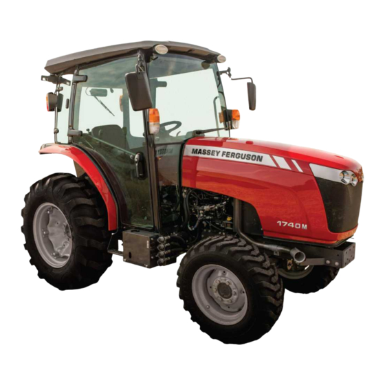
1. General 1.6 Machine main components GUID-8C1D47C5-C0DA-4CA9-8CE2-8E86679E4BE1 [V2] 1.6.1 Cab tractor major components 14 15 16 TRDHE0110208202 GUID-19DE43DC-3F6F-4AAB-B4A0-800460C00964-low.svg [Low] Fig. 51 Turn/warning lamps (15) Front axle pivot Original art: /s/TECHNICL/2013 CMS Graphics/__Raw Graphics/Crystal Hoffman/1700 Series Compact Tractor/MF1700 (Premium_Power Shift type) illustration/B-6_Fig5.tif Reflector (16) Steering cylinder Lift arm... -
Page 50: Platform Tractor Major Components
1. General GUID-4CA166B1-7809-4BEC-A449-5C80BF6306F0 [V2] 1.6.2 Platform tractor major components 15 16 17 TRDHE0110208302 GUID-894BD613-87D5-4436-B437-02819E9C55A3-low.svg [Low] Fig. 52 Turn/warning lamp (15) Front axle Original art: /s/TECHNICL/2013 CMS Graphics/__Raw Graphics/Crystal Hoffman/1700 Series Compact Tractor/MF1700 (Premium_Power Shift type) illustration/B-7_Fig6.tif Roll over protective structure (16) Front axle pivot Reflector (17) Steering cylinder... - Page 51 This as a preview PDF file from best-manuals.com Download full PDF manual at best-manuals.com...
Need help?
Do you have a question about the Massey Ferguson 1700M Series and is the answer not in the manual?
Questions and answers
I have a 1760M What is the engine oil capacity. What viscosity