Riello RL 250 MZ Installation, Use And Maintenance Instructions
Light oil burners
Hide thumbs
Also See for RL 250 MZ:
- Installation, use and maintenance instructions (53 pages) ,
- Installation, use and maintenance instructions (53 pages) ,
- Installation, use and maintenance instructions (53 pages)

Subscribe to Our Youtube Channel
Related Manuals for Riello RL 250 MZ


Summary of Contents for Riello RL 250 MZ
- Page 1 Installation, use and maintenance instructions 安装、使用及维护手册 Light oil burners 轻油燃烧器 Two-stage operation 两段火运行 CODE - 编码 MODEL - 型号 TYPE - 类型 20044403 RL 250 MZ 970 T 20044425 (2) - 05/2013...
-
Page 3: Table Of Contents
CONTENTS Technical data........page 2 List of available models ....... . 3 Burner description . -
Page 4: Technical Data
TECHNICAL DATA MODEL RL 250 MZ TYPE 970 T OUTPUT 2nd stage 1250 ÷ 2700 (min - max) kg/h 106 ÷ 228 DELIVERY 1st stage (min) kg/h FUEL LIGHT OIL - net calorific value kWh/kg 11.8 Mcal/kg 10.2 (10.200 kcal/kg) - density 0.82 - 0.85... -
Page 5: List Of Available Models
3N / 400V / 50Hz 3/230/50 3 / 230V / 50Hz Auxiliary voltage : 230/50/60 230V / 50-60Hz 110/50/60 110V / 50-60Hz 3/400/50 230/50/60 BASIC DESIGNATION EXTENDED DESIGNATION LIST OF AVAILABLE MODELS Designation Electrical supply Starting Code RL 250 MZ 400V-50Hz Direct 20044403... -
Page 6: Burner Description
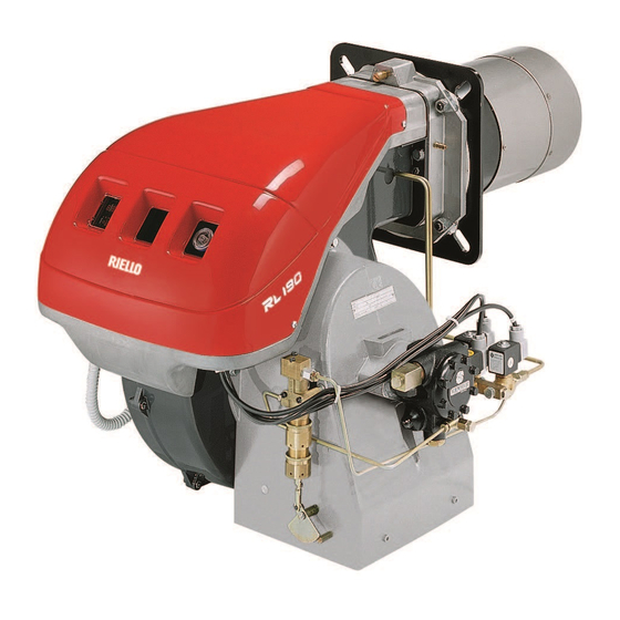
BURNER DESCRIPTION (A) 1 Fan 2 Fan motor 3 Air gate valve servomotor 4 Combustion head 5 Ignition electrodes 6 Flame stability disk 7 Panel board - cover 8 Air inlet to fan 9 Manifold 10 Thermal insulation screen for securing burner to boiler 11 Shutter 12 Air pressure test point... -
Page 7: Packaging - Weight
• The burner stands on a wooden base which can be lifted by fork-lifts. Outer dimensions of packaging are indicated in (A). RL 250 MZ 1400 1040 • The weight of the burner complete with pack- aging is indicated in Table (A). -
Page 8: Firing Rates
EN 267 regulations. Figure (B) indicates the diameter and length of the test combustion chamber. Example: 1600 1200 2000 2400 2800 3200 RL 250 MZ burner Output 1770 kW: diameter 80 cm - length 3 m. D3944 0,25 kg/h D1637... -
Page 9: Installation
(A). The position of the threaded holes can be marked using the thermal screen sup- plied with the burner. RL 250 MZ 325 - 368 BLAST TUBE LENGTH (B) The length of the blast tube must be selected... -
Page 10: Nozzle Assembly
NOZZLE ASSEMBLY Fit two nozzles with the box spanner 1)(A) (16 mm), after having removed the plastic plugs 2)(A), fitting the spanner through the central hole in the flame stability disk. Do not use any sealing products such as gas- kets, sealing compound, or tape. -
Page 11: Fuel Supply
FUEL SUPPLY Double-pipe circuit (A) The burner is equipped with a self-priming pump which is capable of feeding itself within the limits listed in the table at the side. The tank higher than the burner A The distance "P" must not exceed 10 meters in order to avoid subjecting the pump's seal to excessive strain;... -
Page 12: Pump
PUMP PUMP 1 - Suction G 1/2" SUNTEC TA 2 2 - Return G 1/2" 3 - Pressure gauge attachment G 1/8" 4 - Vacuum meter attachment G 1/8" 5 - Pressure adjustment screw 6 - By-pass screw A - Min. delivery rate at 12 bar pressure B - Delivery pressure range C - Max. -
Page 13: Servomotor
SERVOMOTOR (A) SERVOMOTOR The servomotor, by means of connection mech- anisms, simultaneously regulates air pressure and delivery and the flow of fuel in use. It features adjustable cams that operate as many switches. Cam 1: blue Limits servomotor travel to 0° position. With the burner off, the air damper is fully closed. -
Page 14: Air Pressure Switch
AIR PRESSURE SWITCH (A) CO CHECK AIR PRESSURE SWITCH Adjust the air pressure switch after having per- formed all other burner adjustments with the air pressure switch set to the start of the scale (A). With the burner working at MIN output, insert a combustion analyser in the stack and slowly close the fan suction line inlet (for example, with cardboard) until the Bacharach index is equal... -
Page 15: Final Checks
FINAL CHECKS • Obscure the photocell and switch on the ther- mostats/pressure switches: the burner should start and then lock-out about 5 s after opening of the 1st stage operation valve. • Illuminate the photocell and switch on the ther- mostats/pressure switches: the burner should start and then go into lock-out after about 10 s. -
Page 16: Burner Operation
BURNER OPERATION BURNER STARTING (A) - (B) Starting phases with progressive time intervals shown in seconds: • Thermostat/pressure switch TL closes. After about 3s: • 0 s : The control box starting cycle begins. • 2 s : The fan motor starts. Servomotor (12) stage position. -
Page 17: Start-Up Cycle Diagnostics
BURNER START-UP CYCLE DIAGNOSTICS During start-up, indication is according to the followig table: COLOUR CODE TABLE Sequences Colour code Pre-purging Ignition phase Operation, flame ok Operating with weak flame signal Electrical supply lower than ~ 170V Lock-out Extraneous light Key: Yellow Green RESETTING THE CONTROL BOX AND USING DIAGNOSTICS... -
Page 18: Faults - Probable Cause - Suggested Remedy
SIGNAL FAULT PROBABLE CAUSE SUGGESTED REMEDY No blink The burner does not - No electrical power supply ......Close all switches - Check fuses - The thermostat/pressure switch TL is open . -
Page 19: Accessories
ACCESSORIES (optional) Code 3010322 • STATUS (see page 17) Code 3002719 • DIAGNOSTICS INTERFACE KIT Code 3000779 • SILENCER BOX KIT Code 3010422 • LONG HEAD KIT • RADIO DISTURBANCE PROTECTION KIT If the burner is installed in places particularly subject to radio disturbance (emission of signals Code 3010386 exceeding 10 V/m) owing to the presence of an INVERTER, or in applications where the length of the thermostat connections exceeds 20 metres, a protection kit is available as an interface... -
Page 20: Appendix
NOTES The RL 250 MZ burner has been type- approved for intermittent operation. This means it shoulds compulsorily be stopped at least once every 24 hours to enable the control box to perform checks of its own efficiency at start-up. Burner halts are normally provided for automatically by the boiler load control system. - Page 21 目录 技术数据 ..... . . 页 2 可订货型号列表 ........3 燃烧器描述...
-
Page 22: 技术数据
技术数据 型号 RL 250 MZ 类型 970 T 出力 2 段火 1250 ÷ 2700 kg/h 106 ÷ 228 ( 最小 - 最大 ) 流量 1 段火 kg/h ( 最小 ) 燃料 轻油 - 净热值 kWh/kg 11.8 Mcal/kg 10.2 (10.200 kcal/kg) - 密度... -
Page 23: 可订货型号列表
连续运行 ( 每 72 小时停机一次 ) 系统电源 : 3/400/50 3N / 400V / 50Hz 3/230/50 3 / 230V / 50Hz 控制电源电压 : 230/50/60 230V / 50-60Hz 110/50/60 110V / 50-60Hz 3/400/50 230/50/60 基本含义 扩展含义 可订货型号列表 型号 电源 启动 编码 RL 250 MZ 400V-50Hz 直接启动 20044403... -
Page 24: 燃烧器描述
燃烧器描述 (A) 1 风机 2 风机电机 3 风门挡板伺服电机 4 燃烧头 5 点火电极 6 稳焰盘 7 配电盘 - 保护罩 8 风机进风口 9 多歧管 10 安装燃烧器到锅炉用隔热垫 11 调节阀 12 风压测试点 13 油泵 14 光电管 15 油泵电机 16 电磁阀组 17 调节燃烧头用螺丝 配电盘描述 (B) 1 风压开关... -
Page 25: 包装 - 重量
包装 - 重量 (A) - 大概值 燃烧器整机放置于能由叉车吊起的木质底盘 • 上。其带包装的外观尺寸如 表 (A) 所示。 燃烧器带外包装的整体重量如表 (A) 所示。 • RL 250 MZ 1400 1040 标准配置 1 - 隔热垫 4 - 将带法兰的燃烧筒安装到锅炉用螺丝:M 16 x 40 1 - 操作手册 1 - 零部件目录 最大尺寸 (B) - 大概值... -
Page 26: 出力范围
如果必须将燃烧器安装在未经 CE 认证的锅炉上 且 / 或锅炉炉膛尺寸明显小于图 (B) 所示,请咨 询制造商。 测试锅炉 (B) 出力曲线根据 EN 676 标准在专用测试锅炉上获 得。 图 (B) 为测试锅炉的炉膛直径及长度。 举例 : RL 250 MZ 型燃烧器 出力 1770 kW ; 直径 80 cm - 长度 3 m。 1600 1200 2000 2400 2800... -
Page 27: 锅炉法兰
安装 锅炉法兰 (A) 如 (A) 所示,在锅炉门上钻孔。随燃烧器提供的 隔热垫可帮助确定螺栓孔的位置。 RL 250 MZ 230 325 - 368 燃烧筒长度 (B) 必须根据锅炉生产商提供的数据选择合适长度的 燃烧筒,且在任何情况下其长度必须大于锅炉门 加炉补的厚度之和。 带前烟道 1) 或中心回焰炉膛的锅炉,其使用耐火 材料制成的保护性炉补 5) 必须装于锅炉炉补 2 和 D455 燃烧筒 4 之间。 此保护性炉补不得妨碍取下燃烧筒。 带水冷却前板的锅炉,则不需要耐火材料制成的 炉补 2)-5)(B),除非锅炉制造商另有要求。 固定燃烧器到锅炉上 (B) • 将隔热垫 ( 标准配置 ) 安装到燃烧筒 4) (B) 上。... -
Page 28: 喷嘴安装
喷嘴安装 在取下塑料塞子 2)(A) 后,用 16 mm 扳手 1) (A) 安装两个喷嘴,将扳手伸入火焰稳定盘的中心 孔。 请勿使用任何密封材料,如密封垫、复合密封材 料或密封胶带。注意不要损坏喷嘴的密封座。安 装时必须将喷嘴拧到位,但不要拧脱扣。 1 段火运行时的喷嘴位于点火电极下,如图 (B) 如果确需在燃烧器未从锅炉上拆下时更换喷嘴, 则需按以下程序进行操作: - 按图 (C) p. 7 所示,沿滑杆拉出燃烧器。 - 拆下螺母 1)(D) 和稳焰盘 2)(D)。 - 使用扳手 3)(D) 更换喷嘴。 电极位置 (B) 确认电极位置如图 (B) 所示。 D691 燃烧头设定... -
Page 29: 燃料供应
燃料供应 双管回路 (A) 燃烧器配置一台自吸泵,可对燃烧器自动送油。 自吸泵的高度见左表。 高位油箱 A 为了避免破坏油泵密封,高度 “P”不能超过 10 米;为了即使在油箱油量极少的情况下能也启动 油泵,高度 “V”不能超过 4 米。 低位油箱 B 油 泵 吸入 口 真空 度 不能 超 过 0.45 bar (35 cm Hg),真空度过高会造成燃油汽化,油泵启动噪音 大,且会降低油泵寿命。 保持燃烧器回油管和进油管在相同水平高度,这 样可以避免进油管吸不到油。 循环回路 循环回路是一个闭合管路,燃油在压力下从油箱 引出,经过一个循环油泵再回到油箱。从此闭合 L (m) D3949 管路中引出一个支管来为燃烧器供油。这一循环... -
Page 30: 油泵启动
油泵 油泵 1 - 进油管 G 1/2" SUNTEC TA 2 2 - 回油管 G 1/2" 3 - 压力表表座 G 1/8" 4 - 真空计表座 G 1/8" 5 - 压力调节螺丝 6 - 旁路螺丝 A - 气压为 12 bar 时的最小供油量 B - 供油压力范围 C - 油泵吸入口最大真空度... -
Page 31: 伺服电机
伺服电机 (A) 伺服电机 伺服电机,通过机械连接方式,同时调节风压、 风量以及所需燃气量。 各种调节通过控制各开关的凸轮实现。 凸轮 1: 蓝 限定伺服电机角度至 0° 位置。燃烧器停机时,风 门挡板完全关闭。 凸轮 2: 橙 调整风门挡板位置至 1 段火或预吹扫位置 ( 工厂 设定为 30° 位置 )。 凸轮 3: 红 调节风门挡板至 2 段火运行位置, 不超过 90° ( 工 厂设定为 90°)。 凸轮 4: 黑 监测... -
Page 32: 风压开关
风压开关 (A) - CO 检测 风压开关 在进行上述燃烧器各部分调节时,风压开关置于 量程 (A) 的开始位置。上述所有调整结束后,方 可调节风压开关。 燃烧器处于最大出力时,在烟囱中插入一个烟气 分析仪,然后缓慢减小风机入口 ( 如可使用厚纸 板遮挡 ),直至黑度 Bacharach 指数等于 2。 顺时针转动压力调节手柄,增大压力直至燃烧器 锁定。 确认箭头向上所指刻度 (A) 位置。再次顺时针旋 转手柄,直至刻度盘上所示值与箭头向下所指位 置 (A) 一致,恢复压力开关的迟滞,用在两个箭 头之间的蓝底白色标记显示。 重新检查燃烧器启动是否正确。 如果燃烧器再次锁定,将手柄逆时针旋转一点。 D3951... -
Page 33: 最终检查
最终检查 • 遮蔽光电管, 闭合温控器 / 压力开关 : 燃烧器应 启动,然后在 1 段火电磁阀开启 5 秒后锁定。 • 照亮光电管, 闭合温控器 / 压力开关 : 燃烧器应 启动,且大约 10 秒后锁定。 • 燃烧器处于 2 段火运行时遮蔽光电管 , 应按顺序 发生以下情况 :火焰在 1 秒内熄灭,吹扫大约 20 秒,点火大约 5 秒,燃烧器锁定。 • 燃烧器运行时,断开安全控制装置 TS 后,再断 开调节控制装置... -
Page 34: 燃烧器运行
燃烧器运行 燃烧器启动 (A) - (B) 启动阶段中,程序时间以秒显示: • 温控器 / 压力开关 TL 闭合。 大约 3 秒后: • 0 秒 : 控制盒启动周期开始。 • 2 秒 : 风机电机启动。 伺服电机 (12) 启动, 风门 挡板开启至 1 段火位置。 • 3 秒 : 点火变压器打火。 油泵 3) 从油箱中吸入燃油, 通过油管 1) 和过滤 器... -
Page 35: 燃烧器启动周期诊断
燃烧器启动周期诊断 启动阶段各项指示如下表: 颜色编码表 顺序 颜色编码 预吹扫 点火阶段 运行,火焰良好 运行,火焰信号弱 电源电压低于 ~ 170V 锁定 外部光源 图例 : 停机 黄色 绿色 红色 复位控制盒及故障诊断 控制盒具有诊断功能,因此很容易确定故障原因 ( 指示器:红色 LED)。 要使用这一功能,必须等进入安全状态 ( 锁定 ) 至少 10 秒之后再按下复位键超过 3 秒。 控制盒会连续闪烁 ( 间隔 1 秒 ), 每组闪烁间隔 3 秒。 注意信号灯的闪烁次数,并确定可能的故障原因。复位需按住按钮... -
Page 36: 故障 - 可能的原因 - 解决方案
信号 故障 可能的故障原因 解决方案 无闪烁 燃烧器不启动 - 无电源 ......闭合所有开关 - 检查保险丝 - 温控器 / 压力开关 TL 开启 ....调整或更换 - 温控器... - Page 37 配件 ( 可选 ) • 状态面板 ( 见第 17 页 ) 编码 3010322 编码 3002719 • 诊断界面组件 编码 3000779 • 消音柜 • 加长燃烧头 编码 3010422 • 抗电磁干扰组件 编码 3010386 安装 “变频器”后 , 如果燃烧器的安装位置受电磁干扰 (信号强度超过 10 V/m) ,或安装时温控器接线长度超过 20 米,需在控制盒和燃烧器间加装一个防护组件。...
-
Page 38: 配件17 附录 配电盘接线图
A - 风机电机 B - 伺服电机 C - 油泵电机 D - 安全电磁阀 E - 1 段火电磁阀 F - 2 段火电磁阀 D3942 注意 RL 250 MZ 型燃烧器为间歇式运行即至少每 24 小时强制停机一次以便对控制盒进行自检, 确保其功能的有效性。 正常情况下, 锅炉负荷控制系统 会自动将燃烧器停机。 如果不是这种情况,则需在燃烧器中串联一个定时器以保证燃烧器至少每 24 小时停机一次。 电气连接必须由具有资质的技术人员操作,且必须符合安装地的强制标准。 因改变本手册电气连接图或电气连接与图不符而造成的后果,利雅路公司将不承担任何责任。 警告 在电气连接中勿将零线与火线接反。 配电盘连接图... - Page 42 KEY TO ELECTRICAL LAYOUT 电气接线图图例 Control box 控制盒 Fan motor thermal cut-out 风机电机热断路器 Photocell 光电管 Remote lock-out signal 远程锁定信号 1st stage hourcounter 1 段火计时器 2nd stage hourcounter 2 段火计时器 Burner manual stop switch 燃烧器手动停止开关 Burner on voltage free contact relay 燃烧器运行无源触点继电器...
- Page 44 Registered Office - 公司注册所在地 : 生产场所 : Manufacturing site: RIELLO S.p.A. Riello Heating Equipment (Shanghai) CO., LTD Riello Heating Equipment (Shanghai) CO., LTD 利雅路热能设备 ( 上海 ) 有限公司 I-37045 Legnago (VR) No. 388, Jinbai Road - Jinshan Industrial Zone 上海市金山工业区金百路 388 号...
Need help?
Do you have a question about the RL 250 MZ and is the answer not in the manual?
Questions and answers