Table of Contents
Advertisement
Quick Links
Advertisement
Table of Contents

Subscribe to Our Youtube Channel
Related Manuals for STI CMCP700S-CVT Series

Summary of Contents for STI CMCP700S-CVT Series
- Page 1 CMCP700S-CVT Series User Manual Ver. 1.1 Released July 27, 2021...
-
Page 2: Table Of Contents
Table of Contents Description Power Opening the Case Configuring the Transmitter Engineering Unit Selection Full Scale Range Settings Low Pass Filter Settings Temperature Output Buffered Output Sensor Fault Detection 4-20mA Outputs Wiring Terminal Pin Assignments Dimensions Troubleshooting Maintenance and Calibration Technical Specifications... -
Page 3: Description
Description The CMCP700S-CVT is compatible with all industry standard IEPE Accelerometers and Piezo-Velocity transducers. Each transmitter provides constant current power for the associated sensor and processes the signal through a True RMS detector to determine the overall amplitude in terms of Acceleration or Velocity. A 4-20mA output proportional to one of the three user selectable ranges can then be sent to the plant’s PLC, DCS, SCADA or other control system to allow operations and maintenance staff to view real time machinery health, set alarms and trigger machine shutdowns for scheduled preventative maintenance. -
Page 4: Engineering Unit Selection
Engineering Unit Selection Engineering Units are selected based on the sensor used in conjunction with the transmitter and the desired output. When using an IEPE accelerometer, choose either A-A, for a g’s Acceleration output, or A-V for an output in terms of Velocity. -
Page 5: Low Pass Filter Settings
Low Pass Filter Selection The CMCP700S-CVT’s bandwidth is controlled by switches LP1 and LP2. Both switches should always in either on or off. The filters are based on ISO 2372 (10816) standards for machines which operate in the 600 to 12,000 RPM Range. -
Page 6: Terminal Pin Assignments
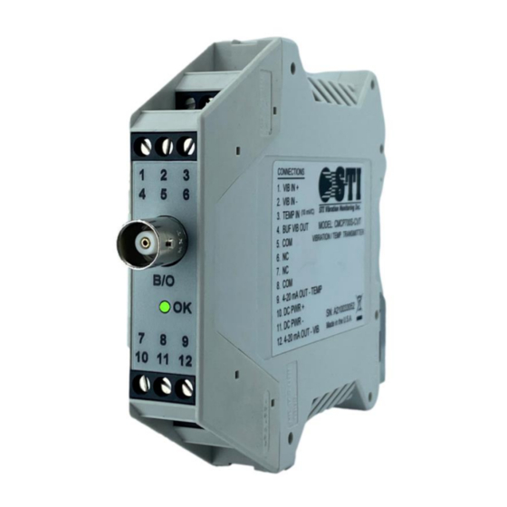
Terminal Block Pin Assignments Input/Output Terminal Number Labeling Function Sensor Input VIB + Signal Input / Sensor Power VIB - Sensor Input Common TEMP IN Temperature Input (10mV/°C) Buffered Output BUF VIB Buffered Dynamic Output Signal Buffered Output Common Analog Outputs Common 4-20 OUT TEMP 4-20mA Output - Temperature... -
Page 7: Troubleshooting
Troubleshooting OK Light Off: Check +24VDC power at bottom left terminals. If +24VDC is good, replace transmitter. OK Light Red: Check to be sure sensor is wired properly to top left terminals. OK Light will turn on WITHIN 3 seconds if sensor is OK. If OK Light stays red, check sensor bias voltage or replace sensor. - Page 8 Revision History Revision Release Date Updates July 2, 2021 Manual Release July 27, 2021 OK fault detection circuit...
Need help?
Do you have a question about the CMCP700S-CVT Series and is the answer not in the manual?
Questions and answers