Sign In
Upload
Download
Table of Contents
Contents
Add to my manuals
Delete from my manuals
Share
URL of this page:
HTML Link:
Bookmark this page
Add
Manual will be automatically added to "My Manuals"
Print this page
×
Bookmark added
×
Added to my manuals
Manuals
Brands
Phcbi Manuals
Freezer
MDF-137 Series
Operating instructions manual
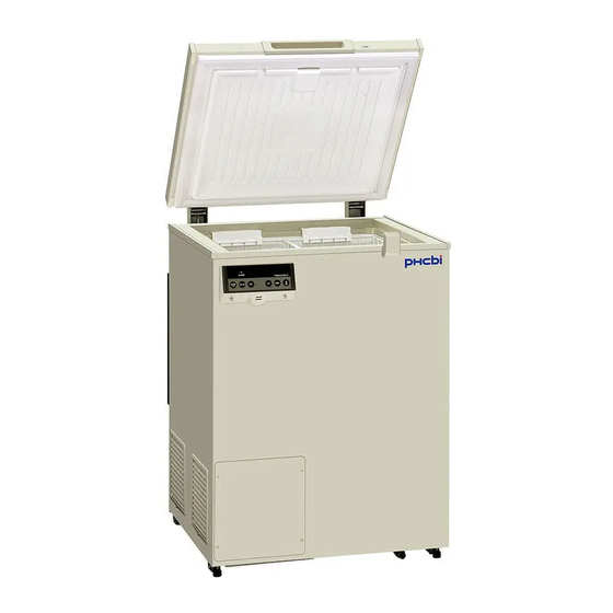
Phcbi MDF-137 Series Operating Instructions Manual
Biomedical freezer
Hide thumbs
1
2
Table Of Contents
3
4
5
6
7
8
9
10
11
12
13
14
15
16
17
18
19
20
21
22
23
24
25
26
27
28
29
30
31
32
33
34
35
36
37
38
39
40
page
of
40
Go
/
40
Contents
Table of Contents
Troubleshooting
Bookmarks
Table of Contents
Table of Contents
Introduction
Precautions for Safe Operation
Environmental Conditions
Labels on Unit
Symbols on Unit
Freezer Components
Control Panel
Installation Site
Installation
Start-Up of Unit
Remote Alarm Terminal
Chamber Temperature Setting
Key Lock Function
Alarm Temperature Setting
Setting of Alarm Resume Time
Change of Compressor Delay Time
Alarms & Safety Functions
Routine Maintenance
Cleaning of Cabinet
Defrosting
Troubleshooting
Disposal of Unit
Recycle of Battery
Decontamination of Unit
Disposal of Battery
Temperature Recorder (Option)
Installation of MTR-4015LH and MTR-G85C
Setting of MTR-4015LH
Setting of MTR-G85C
Interface Board (Option)
Specifications
Performance
Safety Check Sheet
Advertisement
Quick Links
1
Specifications
Download this manual
Please read the operating instructions carefully before using this product, and keep the operating
instructions for future use.
See page 33 for all model numbers.
Operating Instructions
MDF-437
Biomedical Freezer
MDF-137
MDF-237
MDF-437
Series
Table of
Contents
Previous
Page
Next
Page
1
2
3
4
5
Advertisement
Table of Contents
Need help?
Do you have a question about the MDF-137 Series and is the answer not in the manual?
Ask a question
Questions and answers
Related Manuals for Phcbi MDF-137 Series
Freezer Phcbi MDF-1156 Series Operating Instructions Manual
Ultra-low temperature freezer (36 pages)
Freezer Phcbi MDF-DU702VH Operating Instructions Manual
Ultra-low temperature freezer (60 pages)
Freezer Phcbi MDF-DU300H Operating Instructions Manual
Ultra-low temperature freezer (48 pages)
Freezer Phcbi MDF-C2156VAN Series Operating Instructions Manual
Ultra-low temperature freezer (44 pages)
Freezer Phcbi MDF-C2156VANC Series Operating Instructions Manual
Ultra-low temperature freezer (44 pages)
Freezer Phcbi MDF-DU901VHL Series Operating Instructions Manual
Ultra-low temperature freezer (64 pages)
Freezer Phcbi MDF-MU339 Operating Instructions Manual
Biomedical freezer (40 pages)
Freezer Phcbi MDF-MU539 Operating Instructions Manual
Biomedical freezer (40 pages)
Freezer Phcbi MDF-U700VX Series Operating Instructions Manual
Ultra-low temperature freezer (52 pages)
Freezer Phcbi MDF-DU702VHA Operating Instructions Manual
(60 pages)
Freezer Phcbi MDF-DU702VXC Operating Instructions Manual
Ultra-low temperature freezer (60 pages)
Freezer Phcbi MDF-U74V Series Operating Instructions Manual
Ultra-low temperature freezer (44 pages)
Freezer Phcbi MDF-U74V Operating Instructions Manual
Ultra-low temperature freezer (44 pages)
Freezer Phcbi MDF-DC500VX Operating Instructions Manual
Ultra-low temperature freezer (300 pages)
Freezer Phcbi MDF-MU549DHL Operating Instructions Manual
Biomedical freezer (36 pages)
Freezer Phcbi MDF-MU539HL Series Operating Instructions Manual
Biomedical freezer (40 pages)
This manual is also suitable for:
Mdf-237 series
Mdf-437 series
Table of Contents
Print
Rename the bookmark
Delete bookmark?
Delete from my manuals?
Login
Sign In
OR
Sign in with Facebook
Sign in with Google
Upload manual
Upload from disk
Upload from URL


Need help?
Do you have a question about the MDF-137 Series and is the answer not in the manual?
Questions and answers