
Related Manuals for Avedro Mosaic KXL UV


Summary of Contents for Avedro Mosaic KXL UV
- Page 2 The Mosaic System may be covered by one or more patent applications issued or pending in the United States and worldwide. Avedro logo design is a registered trademarks of Avedro, Inc. All software and documentation is subject to Avedro, Inc. copyrights. All rights reserved 2015.
- Page 3 Chapter: Forward ..................... 1-1 Intended Use of Manual ................. 1-1 Intended Use / Indications for Use..............1-1 Essential Requirements .................. 1-1 Design Change Disclaimer ................1-1 Reproduction Disclaimer ................1-1 User Operation Assistance Statement ............1-1 Contraindications, Warnings and Cautions............ 1-2 1.7.1 Contraindications ................
- Page 4 4.4.4 Multiple Treatment Order ..............4-4 Treatment Activation Card ................4-5 4.5.1 Multi-use disposables ................. 4-5 4.5.2 Treatment Activation Card Limit ............4-6 Set Riboflavin Induction Period..............4-6 Preparing the Patient ..................4-7 Apply Riboflavin ................... 4-7 Coarse Alignment with Laser Crosshairs ............4-8 4.10 Visual Axis Marker Alignment Mode (No topography import) ....
- Page 5 Figure 2-1. Overview Illustration of System with Callouts ..............2-2 Figure 2-2. Mosaic Label........................2-3 Figure 2-3. UV emitting Label ........................ 2-3 Figure 2-4 Laser Classification Label ...................... 2-3 Figure 2-5 Do Not Sit or Step on Label ....................2-3 Figure 3-1 Lift Buttons ...........................
- Page 6 This manual is designed to serve the operators of the Avedro, Inc. Mosaic System. All operating instructions, product illustrations, screen graphics, troubleshooting/error messages, and other relevant information are contained in this manual. It is the operator’s responsibility to ensure that all safety instructions in this manual are strictly followed.
- Page 7 Epithelial healing disorders For Equipment Classifications please refer to chapter 7: Equipment Classifications WARNING: Any repair or service must be carried out by Avedro trained personnel only. WARNING: Do NOT modify this equipment without authorization of the manufacturer. WARNING: To avoid the risk of shock this equipment must only be connected to a supply mains with protective earth.
- Page 8 Chapter 1: Forward WARNING: Remove the wall plug and turn off the power switch before servicing or cleaning (disinfecting) the equipment. Never pull cords to remove the power cord from the outlet. Grasp the power cord plug and pull it from the outlet to disconnect. WARNING: Do not operate the equipment with a damaged power cord.
- Page 9 Properly shielded and grounded cables and connectors must be used in order to meet FCC emission limits. Proper cables and connectors are available from Avedro. Avedro is not responsible for any radio or television interference caused by unauthorized changes or modifications to this equipment.
- Page 10 The Mosaic System is an electronic medical device which delivers ultraviolet light (365 nm wavelength) in a programmable pattern onto the cornea after a solution of ophthalmic riboflavin solution has been applied. UV flux and irradiation time (i.e., fluence) at the cornea are controlled by an onboard computer system.
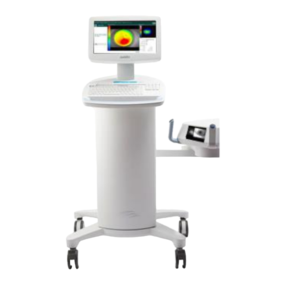
- Page 11 Chapter 2 : Introduction Figure 2-1. Overview Illustration of System with Callouts Main Console with USB flash drive and treatment activation slot System Keyboard System Body with lift system Articulating Arm Heads Up Display Optical Head Stand by Switch Wheels Mosaic System Operator’s Manual, ML-00023 Rev A...
- Page 12 Chapter 2: Introduction Figure 2-2. Mosaic Label Figure 2-3. UV emitting Label Figure 2-4 Laser Classification Label Figure 2-5 Do Not Sit or Step on Label Mosaic System Operator’s Manual, ML-00023 Rev A...
- Page 13 Chapter 2 : Introduction FUNCTION MODE SECTION Turn System On Press Stand By switch under the keyboard in the front of the Mosaic console Select ‘‘Power Off’ on main console display Go on Stand By 4.13 Select ‘‘Design OD’’/ ‘‘Design OS’’. This Treatment Design initiates a new treatment design.
- Page 14 Chapter 2: Introduction Unpacking and installation of the Mosaic system should ONLY be carried out by trained Avedro personnel. The table below identifies and describes important touchpad keys and icons unique to Mosaic System operation. Touchpad Key Icon Description/Function Power...
- Page 15 Chapter 2 : Introduction The UV Energy (Dose) is the product of the UV Power (Intensity) and the UV Irradiation Time. The UV Energy, UV Power and pulsing times are adjustable and the calculated total treatment time is displayed. ...
- Page 16 3 System Set Up CAUTION: Only qualified and experienced personnel initially trained by Avedro shall operate the Mosaic System. The user is responsible for assuring that the Mosaic System is functioning properly, is within normal operating ranges for temperature and humidity, and is in good-working condition before starting a treatment.
- Page 17 Chapter 3 : System Set Up Recall Positions Main Button Up (+) and Down (-) Figure 3-1 Lift Buttons There are three memory recall positions. Factory default for (1) , (2) and (3) set to lower height, mid height and upper height positions respectively. The user can store a user- specific height in the memory for future use.
- Page 18 Chapter 3: System Set Up Moving the lift of the optical head too far down may trigger a proximity sensor. This is a safety feature for the optical head not to get too close to the patient’s head. If the proximity sensor is triggered, the lift will stop responding and a warning will flash on the screen.
- Page 19 Chapter 3 : System Set Up Figure 3-4. Startup Screen NOTE: If there is a Start-up error, please note any error messages and contact your distributor or Customer Service immediately. NOTE: Screen shots are for demonstration purposes only and may have slight modifications.
- Page 20 Patient central is the main page where patient information can be imported or new patient files can be created. No information is stored on the system, but is instead saved on the USB flash drive. Patient topographies can be imported via the patient central from the USB flash drive for guided treatment patterns.
- Page 21 Chapter 4 : Treatment Procedure John Mary John Mara Johnny Jack Figure 4-1. Import/Enter Patient Data Screen Select the patient to be treated. Select ‘‘Design OD’’ or ‘‘Design OS’’ to create right or left eye treatments respectively. This takes the user to the Treatment Design Window.
- Page 22 Chapter 4: Treatment Procedure Figure 4-2 Main Screen Layout Patient Information Design window with map overlay Treatment/Shape Selection Map Settings Treatment change, edit or delete X/Y Coordinate tracking Irradiance power Selection – Indices Continuous/Pulse UV selection Secondary Map Back to Patient Central Left/Right Eye Start New Treatment Select ‘‘Add Shape’’...
- Page 23 Chapter 4 : Treatment Procedure Click or touch on the Main Design Window to place a 9 mm circle. Figure 4-3 Click/Drag to set KXL treatment The circle can then be centered on the limbus, pupil or vertex (if available). If no selection is made, the circle automatically centers around the vertex (for topography imports) or centers around the grid (for no topography imports).
- Page 24 Chapter 4: Treatment Procedure o ellipses of user-defined diameter and axis; o single arcuate sector of user-defined size, thickness and angle; o symmetrical double arcuate sectors of user-defined size, thickness and angle; o annular surface with user-defined diameters; o or, any free-hand user-defined drawn surface. Figure 4-5 Treatment Shape Selection ...
- Page 25 Chapter 4 : Treatment Procedure Figure 4-6 Selecting Energy Dose and Centering Pattern Use the X Position and Y Position to adjust the location or center around the Limbus, Pupil or Vertex by selecting one of the three buttons. ...
- Page 26 Chapter 4: Treatment Procedure In the first treatment summary (Fig 4-8), the higher energy smaller circle has higher priority; therefore, even when the 7 mm circle treatment is complete after 6 minutes, the DMD keeps the smaller circle ‘on’. In the second treatment summary, the 7 mm circle treatment has higher priority. Therefore, when the 6 minute treatment is up, the DMD mirrors in that area shut off since the treatment is up and the resultant treatment resembles the smaller circle with an area cut off.
- Page 27 Chapter 4 : Treatment Procedure Figure 4-9. Activation Card not detected Prior to the final treatment, a message will be displayed to warn the user of only one treatment remaining. Figure 4-10. Final Treatment 4.5.2 Once card has been read, a window will appear (‘‘Confirm Treatment Design & Parameters’’) showing the summary of the treatment parameters similar to Fig 4-8.
- Page 28 Chapter 4: Treatment Procedure NOTE: Default treatment parameters will auto-populate user selectable fields but are adjustable. Ensure that the patient is lying flat on a patient table or chair. His or her head should rest in a head rest. ...
- Page 29 Chapter 4 : Treatment Procedure Pressing the buttons on the handles of the articulating arm to disengage the brakes, steer the optics head over the patient’s head. Align the optics head such that the laser crosshairs are closely aligned/overlapped on each other.
- Page 30 Chapter 4: Treatment Procedure Pressing the buttons on the handles of the articulating arm to disengage the brakes, rotate the optics head such that the visual axis markers are aligned with the horizontal blue line on the Heads Up Display. ...
- Page 31 Chapter 4 : Treatment Procedure Figure 4-15 Start Auto Alignment After the alignment sequence is performed, the user is alerted that alignment is complete. Figure 4-16 Alignment Complete Once alignment is completed, and riboflavin induction is over, the ‘‘Begin UV Treatment’’...
- Page 32 Chapter 4: Treatment Procedure the image of the eye looks more focused. This will facilitate the auto focus algorithm when the user re-starts the auto-alignment process. Figure 4-17 Z-Alignment Error If the iris registration fails, the user is notified of the failure and the user has the option to re-start the auto-alignment or forego auto-alignment and proceed with manual alignment.
- Page 33 Chapter 4 : Treatment Procedure Skipping auto alignment to do manual alignment will provide the user of motor controls to manually align in X-Y and Z direction. WARNING: In case of manual alignment for asymmetrical treatment shapes, the user should manually perform rotational alignment in order to accurately apply the treatment.
- Page 34 Chapter 4: Treatment Procedure Figure 4-21 Begin UV Treatment A Treatment in Progress bar shows the progress of the UV treatment and Treatment Time Remaining, Total Energy Delivered and Total Induction Period are displayed. Figure 4-22 Treatment in Progress ...
- Page 35 Chapter 4 : Treatment Procedure Figure 4-23 Pausing UV Treatment Prior to resuming UV treatment, ensure that the alignment is correct. The user can choose to re-align or proceed without re-aligning and select ‘‘Resume’’ to start the UV irradiation again.
- Page 36 Chapter 4: Treatment Procedure The settings button allows the user to save a report of the treatment parameters to the USB stick. Figure 4-25 Settings to save report Select the “PDF” button. This saves a report to the USB drive. ...
- Page 37 Figure 5-1. Device Settings Menu Advanced Settings are only available to Avedro and Service personnel with a Mosaic Advanced Settings access card. If selected the user will be prompted to scan an access card. Select ‘‘Transfer Data to USB’’ on the Device Settings menu.
- Page 38 Chapter 5 : Advanced Settings Figure 5-2. Device Settings Transfer to USB Insert a USB device to a USB port and then select ‘‘Copy treatment data to USB’’. The system begins transferring the treatment data and shows a progress bar of the transfer process as shown in the screen below.
- Page 39 Per Patient Disposables can be ordered from Avedro or your Avedro-authorized distributor. Use only Avedro products or Avedro-approved products with your Mosaic System. Avedro shall not be liable for damage to or malfunction of the system, which it deems, was caused by the use of unauthorized materials.
- Page 40 Avedro service representative. Interval Specific Task Annual Calibration check by Avedro trained personnel. The Mosaic is designed as a movable system within an office environment. When moving the system, ensure that the articulating arm and the head are retracted close to the monitor as shown in the image below for safe motion from one place to another.
- Page 41 Do not disassemble any part of the system as this could cause misalignment or damage. Should the software become corrupt and fail to work correctly at some point, call your local Avedro service representative. Software updates will only be carried out by Avedro trained service representatives. ...
- Page 42 Chapter 6 : Maintenance / Service When disposing of waste products, residues and Mosaic System and accessories, follow all applicable local regulations or contact an Avedro authorized distributor. Check all components of the device routinely for damage or malfunction prior to each treatment.
- Page 43 7 Equipment Classification According to IEC60601-1:2005+A1:2012 Medical Device Electrical Standard o Protection against electrical shock Class 1 (external electrical power source) o Degree of protection against electric shock Not classified, equipment not provided with applied part o Degree of protection against ingress of water ...
- Page 44 Chapter 7 : Equipment Classification The Mosaic System has been qualified for use with the following cables and accessories. Use of cables, and accessories other than those listed may result in increased emissions or decreased immunity of the Mosaic System. Cables Accessories None...
- Page 45 Chapter 7: Equipment Classification Guidance and manufacturer’s declaration — electromagnetic immunity The Mosaic System is intended for use in the electromagnetic environment specified below. The customer or the user of the Mosaic System should assure that it is used in such an environment.
- Page 46 Chapter 7 : Equipment Classification Guidance and manufacturer’s declaration — electromagnetic immunity The Mosaic System is intended for use in the electromagnetic environment specified below. The customer or the user of the Mosaic System should assure that it is used in such an environment. IEC 60601 test Compliance Electromagnetic environment —...
- Page 47 Chapter 7: Equipment Classification The Mosaic System is intended for use in an electromagnetic environment in which radiated RF disturbances are controlled. The customer or the user of the Mosaic System can help prevent electromagnetic interference by maintaining a minimum distance between portable and mobile RF communications equipment (transmitters) and the Mosaic System as recommended below, according to the maximum output power of the communications equipment.
- Page 48 Chapter 7 : Equipment Classification The Mosaic System contains an RFID function which transmits and receives at the 13.56 MHz frequency. This functionality may be interfered with by other equipment, even if that other equipment complies with CISPR emission requirements. The Mosaic System contains the following RF transmitters: RFID Reader ...
- Page 49 8 Symbol Library Text Symbol Symbol Illustration Definition 1. No AP symbol in presence of Danger, Risk of Explosion. Not flammable anesthetics for use Alternating current 2. AC symbol 3. ‘‘I’’ in a book Attention: Consult ACCOMPANYING DOCUMENTS Protected earth (ground) 4.
- Page 50 Chapter 8: Symbol Library Text Symbol Symbol Illustration Definition 14. Percent sign on sea level Humidity limits (percentages below symbol are the acceptable range for humidity) 15. Temperature limits Temperature shipment limits 16. Reference Number System reference number 17. Serial Number System serial number 18.
- Page 51 9 Specifications Specification Description Electrical Line voltages 100 -- - 240 volts AC, ± 10% Current 10A -- - 5A Single Phase 50/60 Hz, ± 5% Fuse: T 10H, 250V Energy Delivery UV Radiation 10 -- - 100 mW/cm 365 nm External Interfaces USB 2.0 Physical Dimensions...
- Page 52 230 Third Avenue Waltham, MA 02451 Tel: 781-768-3400...
Need help?
Do you have a question about the Mosaic KXL UV and is the answer not in the manual?
Questions and answers