
Related Manuals for DAYE DG600


Summary of Contents for DAYE DG600
- Page 1 Engines Original Instructions Model: DG600 2015 Ningbo Daye Garden Machinery Co., Ltd. No.58 Jinfeng Road, Yuyao, Zhejiang 315403, P.R.China Tel: +86-574-62678966 Fax: +86-574-62678784...
-
Page 2: Table Of Contents
CONTENTS SECTION 1 INTRODUCTION................3 SECTION 2 SAFETY MESSAGES................3 SECTION 3 SAFETY INFORMATION ..............3 SECTION 4 COMPONENT&CONTROL LOCATION..........4 SECTION 5 PRE-OPERATION CHECKS...............4 SECTION 6 OPERATIONS ..................4 SECTION 7 SPECIFICATIONS…………………………………………………………6 SECTION 8 TUNE-UP SPECIFICATIONS..............6 SECTION 9 SERVICING YOUR ENGINE...............7 SECTION 10 ENGINE ADJUSTMENT……………………………………………..14 SECTION 11 HELPFUL TIPS&SUGGESTIONS………………………..…………..14 SECTION 12 TAKING CARE OF UNEXPECTED PROBLEMS...... -
Page 3: Section 1 Introduction
1. INTRODUCTION Thank you for purchasing our engine. We want to help you to get the best results from your new engine and operate it safely. This manual contains information on how to do that; please read it carefully before operating the engine. -
Page 4: Section 4 Component&Control Location
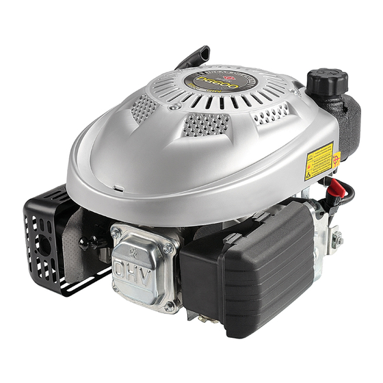
4. COMPONENT&CONTROL LOCATION Fig. 1 1. Starter grip 2. Fuel cap 3.Air filter 4. Carburetor 5.Spark plug 6. Muffler 7. Oil filter cap/dipstick 8.Fuel tank 5. PRE-OPERATION CHECKS For your safety, and to maximize the service life of your equipment, it is very important to take a few moments to check the engine condition before operating. - Page 5 Carbon monoxide gas is toxic. Breathing it can cause unconsciousness and even kill you. WARNING: Avoid any areas or actions that expose you to carbon monoxide. Review the instructions provided with the equipment powered by this engine for any safety precautions that should be observed with engine startup, shutdown, or operation.
-
Page 6: Section 7 Specifications
Fig. 4 2. Turn the fuel valve to the “OFF” position 7. SPECIFICATIONS Type DG600 Dry weight(kg) 14.5 Engine type 4-stroke, overhead valve, single cylinder Displacement[Bore x Stroke] 173cc 70*45mm Max. torque 10N.m at 2,800rpm Cooling system Forced air Lubrication systems... - Page 7 recommendations and schedules in this owner's manual. To help you properly care for your engine, the following pages include a maintenance schedule, routine inspection procedures, and simple maintenance procedures using basic hand tools. Other service tasks that are more difficult, or require special tools, are best handled by professionals and are normally performed by our technician or other qualified mechanics.
- Page 8 Before First Every 3 Every 6 Every Every Regular service period each use month months months year or Note or 5 or 25 hrs or 50 hrs 100 hrs years Item perform at every in dictated month or operating hour interval. 200hrs Whichever comes first √...
- Page 9 Refuel only outdoors. Wipe up spills immediately. Fuel can damage paint and some types of plastic. Be careful not to spill fuel when filling your CAUTION: fuel tank. Damage caused by spilled fuel is not covered under the Warranty. Never use stale or contaminated gasoline or oil/gasoline mixture.
- Page 10 4. If the oil level is near or below the lower limit mark on the dipstick, remove the oil filler cap/dipstick(7), and fill with the recommended oil to the upper limit mark (bottom edge of .the oil fill hole). Do not overfill. 5.
- Page 11 6. Install and tighten dipstick Engine Oil Capacity: 0.60L (0.158US gal, 0.132UK gal) Fig. 9 Running the engine with a low oil level can cause engine damage. Reinstall the oil filler cap/dipstick CAUTION: securely. 9.7 AIR CLEANER A dirty air cleaner will restrict air flow to the carburetor and cause poor engine performance. Inspect the air cleaner each time the engine is operated.
- Page 12 3. Wash the foam element in liquid detergent and water. Squeeze dry the foam element in a clean cloth. 4. Saturate the foam element with clean engine oil. To remove the excess engine oil, squeeze the foam element in a clean cloth. 5.
-
Page 13: Section 10 Engine Adjustment
pulling on the recoil starter. Also verify that the governor arm is moved to the idle (slow), position and there is free play in the cable. The cable should 10~15 mm from the centerline as shown when the cable is new. 4. - Page 14 or completely filled. The air in a partially filled fuel tank promotes fuel deterioration. Very warm storage temperatures accelerate fuel deterioration. Fuel problems may occur within a few months, or even less if the gasoline was not fresh when you filled the fuel tank. Fuel system damage or engine performance problems resulting from neglected storage preparation are not covered under Warranty.
- Page 15 3. Reinstall the fuel strainer (A) and fuel line. (See Fig. 14) Fig. 14 11.1.8 STORAGE PRECAUTIONS If your engine will be stored with gasoline in the fuel tank and carburetor, it is important to reduce the hazard of gasoline vapor ignition. Select a well-ventilated storage area away from any appliance that operates with a flame, such as a furnace, water heater, or clothes dryer.
-
Page 16: Section 12 Taking Care Of Unexpected Problems
TAKING CARE OF UNEXPECTED PROBLEMS ENGINE WILL NOT START Possible Cause Correction 1. Check fuel. Out of fuel. Refuel Bad fuel; engine stored without eating or Drain the fuel tank and draining gasoline, of refueled with bad Carburetor.Refuel With fresh gasoline. - Page 17 13.2 CARBURETOR MODIFICATIONS FOR HIGH ALTITUDE OPERATION 1. At high altitude, the standard carburetor air-fuel mixture will be too rich. Performance will decrease, and fuel consumption will increase. 2. A very rich mixture will also foul the spark plug and cause hard starting. Operation at an altitude that differs from that, at which this engine was certified, for extended periods of time, may increase emissions.
- Page 18 MODELS: M51SPC (DYM1560AQ) COBRA LAWN MOWER OWNER’S MANUAL Cobra Garden Machinery Henton and Chattell Ltd., London Road, Nottingham NG2 3HW UK www.cobragarden.co.uk...
- Page 19 CONTENTS SECTION 1 SYMBOLS MARKED ON THE PRODUCT......... 3 SECTION 2 GENERAL SAFETY RULES............... 3 SECTION 3 PARTS DESCRIPTION..............6 SECTION 4 TECHNICAL DATA................6 SECTION 5 ASSEMBLY..................SECTION 6 “3 IN 1” ....................SECTION 7 OPERATION INSTRUCTIONS ............SECTION 8 MAINTENANCE INSTRUCTIONS…………………………………..…. 12 SECTION 9 LUBRICATION...................
-
Page 20: Section 1 Symbols Marked On The Product
WARNING: For your own safety please read this manual before attempting to operate your new unit. Failure to follow instructions can result in serious personal injury. Spend a few moments to familiarise yourself with your mower before each use. 1. SYMBOLS MARKED ON THE PRODUCT Fig. - Page 21 Never mow while people, especially children or pets are nearby. Never use the mower if the operator is taking medicine or substances that could affect or impair his ability to react or concentrate. Keep in mind that the operator or user is responsible for accidents or hazards occurring to other people or their property. Before you start While mowing, always wear substantial footwear and long trousers.
- Page 22 where a key is fitted remove the key, make sure engine is completely cooled. - Whenever you leave the lawn mower. - Before refuelling. 21. Reduce the throttle setting during engine shut down and, if the engine is provided with a shut-off valve, turn the fuel valve off at the conclusion of mowing.
-
Page 23: Section 3 Parts Description
15. Upper handle 16. Side discharge chute 17. Mulching wedge Including A: Spark plug wrench 4. TECHNICAL DATA Model M51SPC (DYM1660AQ) Engine type DG600 Self Propelled Engine Displacement 173 cm Blade Width 510 mm Speed at max. Power 2800/min Fuel Tank Capacity 2.0L... -
Page 24: Section 5 Assembly
Measured sound power level 93.9 dB(A) K=2.01dB(A) Guaranteed Sound Power level 98 dB(A) (According to 2000/14/EC) Vibration 4.489 m/s² (According to EN 836 Annex G) K=1.5 m/s² 5. ASSEMBLY 5.1 FOLDING HANDLE 1. Fix the lower handlebars into the unit body with a suitable spanner. (Fig. 2A) 2. - Page 25 Apply outward pressure to disengage the lever from the rack. Move the lever forward or back to adjust the height of cut. (Fig. 5 and see clause 7.9) Fig. 5 “3 IN 1” The lawn mower has 3 in 1 features: Rear grass collection.
- Page 26 WARNING : Only when the engine is completely stopped and the blades have stopped rotating. 1. Lift the rear cover and remove the grass catcher. 2. Mount the Mulching wedge. 3. Lift the flap for side discharge. (Fig. 7A) 4. Mount the side discharge channel for side discharge on the support pin of the sideward flap. (Fig. 7B) 5.
- Page 27 Replace all fuel tanks and container caps securely. Before tipping the lawn mower to maintain the blade or drain oil, remove fuel from tank. WARNING: never fill fuel tank indoors, with the engine running or until the engine has been allowed to cool for at least 15 minutes after running.
- Page 28 Grip the Self-drive control handle, the lawnmower will move forward automatically with a speed of about 3.6km/h (Fig.10), release the self-drive handle, the lawnmower will stop moving. Fig. 10 FOR THE BEST RESULTS WHEN MOWING First clear the lawn of debris: Be sure that the grass is clear of stones, sticks, wire or other objects, which could be accidentally thrown out by the mower in any direction and cause serious injury to the operator and others as well as damage to property and surrounding objects.
-
Page 29: Section 8 Maintenance Instructions
7.8 DECK The underside of the mower deck should be cleaned after each use to prevent a buildup of grass clippings, leaves, dirt or other matter. If this debris is allowed to accumulate, it will invite rust and corrosion, and may prevent proper mulching. The deck may be cleaned by tilting the mower and scraping clean with a suitable tool (make certain the spark plug wire is disconnected). - Page 30 CAUTION: Do not allow dirt or dust to clog the air filter foam element. The engine air cleaner element must be serviced (cleaned) after 25 hours normal mowing. The foam element must be serviced regularly if the mower is used in dry dusty conditions. To CLEAN AIR FILTER 1.
-
Page 31: Section 11 Storage Instructions (Off Season)
Fig. 14 10.3 BLADE MOUNTING TORQUE Center Bolt 40Nm.min, 50Nm.max. To ensure safe operation of your unit. All nuts and bolts must be checked periodically for correct tightness. After prolonged use, especially in sandy soil conditions, the blade will become worn and lose some of the original shape. - Page 32 - If the starter rope becomes disconnected from rope guide on the handle, disconnect and ground the spark plug wire. Depress the blade control handle and pull the starter rope out from the engine slowly. Slip the starter rope into the rope guide bolt on the handle.
-
Page 33: Section 12 Troubleshooting
12. TROUBLESHOOTING PROBLEM PROBABLE CAUSE CORRECTIVE ACTION Engine does not start. Throttle chock not in the correct Move throttle choke to correct position position for the prevailing conditions. Fuel tank is empty. Fill tank with fuel: refer to ENGINE OWNERS MANUAL. -
Page 34: Section 13 Warranty
WARRANTY This product is warranted in accordance with legal regulations for a 24 month period effective from the date of purchase by the first user. This product will not be covered if used in a commercial application. This warranty covers all material or production failures, it does not include: defects from normal wear and tear, parts such as, bearings, brushes, cables, air cleaning elements, brake pad, clutch disc, tyre, wheel, recoil starter rope, belts, cutter blades, plugs, lubricant oils and grease or accessories. - Page 35 15. EC Declaration of Conformity EC Declaration of Conformity We herewith declare, Cobra Garden Machinery Henton & Chattell Ltd, London Road, Nottingham NG2 3HW United Kingdom that the following machine complies with the appropriate basic safety and health requirements of the EC Directive based on its design and type, as brought into circulation by us.
Need help?
Do you have a question about the DG600 and is the answer not in the manual?
Questions and answers