
Related Manuals for Quattroflow QF5K


Summary of Contents for Quattroflow QF5K
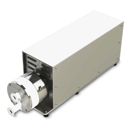
- Page 1 QF5K QF5K-HT QF5KQcon QF5KCD Stainless Steel 4-Piston Diaphragm Pump Operating Manual Translation of original operating manual...
-
Page 2: Table Of Contents
Troubleshooting .......... 40 Table of contents Troubleshooting ......... 40 General information ........3 Return ..........42 Manufacturer and Service ..... 3 Disposal ............42 Exclusion of liability ....... 3 Glossary ..........43 Presentation conventions ..... 3 Pumps ........... 4 Version history ........4 Safety ............ -
Page 3: General Information
The manufacturer will accept no liability for damages and consequential damages resulting from this. Quattroflow is a trade name of PSG Germany GmbH. PSG Germany endeavours to continuously improve the product and reserves the right to make modifications to the technology and/or design without prior notice. -
Page 4: Pumps
General information Pumps This instruction applies for the following pumps: Pump QF5K • Standard motor • Drive: Three-phase current motor 2.2 kW, 400 V • Speed control: external frequency converter (not included in standard scope of delivery) • Eccentric shaft: 5°... -
Page 5: Safety
Safety Safety This chapter contains important information for safe operation of the pump. Intended use Pumping water-like fluids for industrial applications in batch mode. Improper use • Pumping of unsuitable media or fluids, especially media which attack the diaphragm or other parts of the pump. -
Page 6: Personnel Requirements
Safety 2.3.4 Electric current Touching electrical parts can cause a fatal electric shock. • Disconnect the pump from the power supply before working on the pump: Pull out the mains plug. Disconnect all phases of the pump from the mains. •... -
Page 7: Description
Description Description The pump is a machine for pumping fluids that is particularly insensitive to permanent stress and contaminations in the fluid. Designed as a piston diaphragm pump, the pump delivers the fluid in self- enclosed volumes. The diaphragm consists of 4 segments. A connecting ring that is moved back and forth from its centre position by an eccentric shaft activates the segments and creates the stroke movement. -
Page 8: Technical Data
Description Technical data The technical data refer to a standard version of the pump. Special pump versions (e.g. special connectors) may have different data. See the extended documentation. Description Unit QF5K QF5K-HT QF5KQCon QF5KCD Flow rate eccentric shaft 5° max. - Page 9 Description Description Unit QF5K QF5K-HT QF5KQCon QF5KCD Non-product wetted materials (standard): Diaphragm housing 1.4404 cover Bearing housing 1.4404 Base plate 1.4301 Hood 1.4301 Pump speed range 30-1200 13-1200 13-1050 Connection specification (standard): Connector " 1.5" TC Flange diameter 50.5 Internal diameter 34.8...
- Page 10 Description Description Unit QF5K QF5K-HT QF5KQCon QF5KCD Motor/gear: Manufacturer Siemens (standard) Type 1LE1003 CMP80M CMP71M Rated speed 1435 (50 Hz) 3000 3000 Voltage 230/400 Nominal current 7.7/4.4 23.5 13.4 23.5 13.4 13.1 Power Shaft diameter IP protection class Colour 7030...
- Page 11 Description Description Unit QF5K QF5K-HT QF5KQCon QF5KCD Control panel/frequency converter: Optional: Optional: Control Control Control Type Separate Separate Integrated into the housing Control Box Control Box (PQ44P) (PQ50T) 200- 380- 200- 380- 380- Nominal voltage Nominal power Nominal frequency 50-60 Nominal current 10.6...
-
Page 12: Performance Charts
�� �� • �� ratio Conditions • Test fluid water at room temperature • Eccentric shaft 5° • Pressures 0 to 6 bar • New diaphragms and new valves • under standard conditions Figure 1 Performance chart QF5K... - Page 13 Description Figure 2 QF5KCD Figure 3 QF5HT and QF5QCON...
-
Page 14: Sub-Assemblies
Description Sub-assemblies Figure 4 Sub-assemblies QF5K - QF5KACUEGNT Item Designation PQ5A Ring drive (Figure 8 Sub-assembly ring drive PQ5A) QF5C Pump chamber (Figure 9 Sub-assembly pump chamber QF5C) PQ5U Connecting nozzle (Figure 10 Sub-assembly connecting nozzle PQ5U) PQ5E Base plate (Figure 11 Sub-assembly base plate PQ5E, PQ5E-HT, PQ5E-Q) - Page 15 Description Figure 5 Sub-assemblies QF5K-HT - QF5KHT-ACUEGNT Item Designation PQ5A Ring drive (Figure 8 Sub-assembly ring drive PQ5A) QF5C Pump chamber (Figure 9 Sub-assembly pump chamber QF5C) PQ5U Connecting nozzle (Figure 10 Sub-assembly connecting nozzle PQ5U) PQ5E-HT Base plate (Figure 11 Sub-assembly base plate PQ5E, PQ5E-HT, PQ5E-Q)
- Page 16 Description Figure 6 Sub-assemblies QF5KQCon - QF5KQCON-ACUEGNT Item Designation PQ5A Ring drive (Figure 8 Sub-assembly ring drive PQ5A) QF5C Pump chamber (Figure 9 Sub-assembly pump chamber QF5C) PQ5U Connecting nozzle (Figure 10 Sub-assembly connecting nozzle PQ5U) PQ5E-Q Base plate Sub-assembly drive unit PQ5G PQ5G-HT Drive unit (Figure 20 Sub-assembly motor flange PQ5T-) PQ44N-Q...
- Page 17 Description Figure 7 Sub-assemblies QF5KCD - QF5KCD-ACUHG Item Designation PQ5A Ring drive (Figure 8 Sub-assembly ring drive PQ5A) QF5C Pump chamber (Figure 9 Sub-assembly pump chamber QF5C) PQ5U Connecting nozzle (Figure 10 Sub-assembly connecting nozzle PQ5U) PQ50H Rack (Figure 12 Sub-assembly rack PQ50H) PQ50G Drive unit (Figure 13 Sub-assembly drive unit PQ5G)
- Page 18 Description 3.5.1 Ring drive PQ5A Figure 8 Sub-assembly ring drive PQ5A Designations correspond to the included parts list...
- Page 19 Description 3.5.2 Pump chamber QF5C Figure 9 Sub-assembly pump chamber QF5C Designations correspond to the included parts list Torques Figure 9 Sub-assembly pump chamber QF5C Item Designation Clamping ring Pump housing Diaphragm support screw Diaphragm housing cover to pump housing Diaphragm housing cover to valve plate...
- Page 20 Description 3.5.3 Connecting nozzle PQ5U Figure 10 Sub-assembly connecting nozzle PQ5U Designations correspond to the included parts list Base plate PQ5E, PQ5E-HT, PQ5E-Q Figure 11 Sub-assembly base plate PQ5E, PQ5E-HT, PQ5E-Q Designations correspond to the included parts list...
- Page 21 Description 3.5.4 Rack PQ50H Figure 12 Sub-assembly rack PQ50H Designations correspond to the included parts list...
- Page 22 Description 3.5.5 Drive unit PQ5G Figure 13 Sub-assembly drive unit PQ5G Designations correspond to the included parts list 3.5.6 Drive unit PQ5G-HT Figure 14 Sub-assembly drive unit PQ5G-HAT Designations correspond to the included parts list...
- Page 23 Description 3.5.7 Drive unit PQ50G Figure 15 Sub-assembly drive unit PQ50G Designations correspond to the included parts list 3.5.8 Housing PQ5N Figure 16 Sub-assembly housing PQ5N Designations correspond to the included parts list...
- Page 24 Description 3.5.9 Housing PQ44N-HT Figure 17 Sub-assembly housing PQ44N-HAT Designations correspond to the included parts list...
- Page 25 Description 3.5.10 Housing PQ44N-Q Figure 18 Sub-assembly housing PQ44N-Q Designations correspond to the included parts list 3.5.11 Motor flange PQ5T Figure 19 Sub-assembly motor flange PQ5T Designations correspond to the included parts list...
- Page 26 Description 3.5.12 Motor flange PQ5T-HT Figure 20 Sub-assembly motor flange PQ5T-HT Designations correspond to the included parts list...
-
Page 27: Control Panels
All pumps with “QCON” in the article code are equipped with the “QControl” control panel. The control panel is covered by a separate operating manual, therefore see the “QControl manual” for further information. Optional accessories These optional accessories are available for the QF5K and QF5KCD: • Leakage sensor (diaphragm monitoring) •... -
Page 28: Assembly/Installation
Assembly/installation Assembly/installation WARNING – The eccentric shaft rotates in a housing. There is a risk of crushing in the space in between. Disconnect the power supply to the pump. Install the pump in this way: • Securely and stably on a non-slip surface able to bear the weight of the pump. •... -
Page 29: Connections
Assembly/installation Connections 4.4.1 Pipes WARNING – If the the pressure can rise above the maximum permissible pressure of the pump, a pressure relief valve or automatic pressure cut-out is required. Connect the pump with pipes and hoses like this • Suction side Pipes are sufficiently dimensioned. -
Page 30: Commissioning
Commissioning Commissioning Before using for the first time, it might be useful to fill the pump with 0.1 N to 0.5 N NaOH alkaline solution and allow it to soak in. The soaking time depends on the desired result (e.g. depyrogenisation 10 - 20 hours). Adapt the flushing and cleaning procedure to the respective application and check the effect by suitable analytical processes. -
Page 31: Cleaning
► Stop the pump. ► Empty the pump. ► For QF5K-HT and QF5KQcon pumps: Switch the pump off with the main switch (7). The display switches off. WARNING – The fluid can heat up parts of the pump. You could suffer burns! ►... -
Page 32: Replacing Elastomers
Operation 6.4.3 Autoclaving of the pump chamber Autoclaving is sterilisation by thermal treatment under overpressure. The pump chamber may only be autoclaved when the pump chamber has been removed. ► Empty the pump completely. ► Clean the pump according to the fluid. ►... - Page 33 Operation 6.5.2 Disassembling the pump chamber DANGER – Touching electrical parts can cause a fatal electric shock. Disconnect the power supply to the pump. WARNING – The fluid can heat up parts of the pump. You could suffer burns. Allow the pump to cool down. ►...
- Page 34 Operation ► Cut off the assembly shaft at the marked position on the valve ( / QF5C, item 6.2 Figure 9). ► Remove the screws (1 / PQ5U, item 2 Figure 10). ► Remove the connecting nozzles (2 / PQ5U, item 1 Figure 10). ►...
- Page 35 Operation ► Mount the diaphragm together with the diaphragm support (1 / QF5C, item 3; 6.1 Figure 9). ► Mount the diaphragm housing cover (2 / QF5C, item 3 Figure 9). ► Fasten the screws (5 / QF5C, item 10; 11 Figure 9). ►...
- Page 36 Operation ► Remove the threaded pin (1 / PQ5G, item 2 Figure 13) from the coupling half (2). ► Disassemble the coupling half (2 / PQ5G, item 2 Figure 13). ► Remove the screws (3 / PQ5A, item 4 Figure 8). ►...
- Page 37 Operation ► Mount the ring drive together with the coupling half (1 / PQ5A Figure 8; PQ5G, item 2 Figure 13). ► Fasten the screws (2 / PQ5T, item 4 Figure 19). ► Mount the pump chamber (see chapter 0 ►...
- Page 38 Operation 6.5.5 Mounting the pump chamber ► Disconnect the power supply to the pump. ► Mount the pump chamber (QF5C Figure 9). NOTE – You can turn the pump chamber (QF5C Figure 9) in 90° steps so that the position of the connectors on the suction and pressure side fit optimally in the machine.
-
Page 39: Maintenance
Maintenance Maintenance Wearing parts such as, e.g., the diaphragms, valves and O-rings must be checked at regular intervals and replaced regularly in the course of preventive maintenance. The recommended intervals were determined under standardised conditions (fluid water, fluid temperature 20°C, ambient temperature 20°C, flow rate 5000 lph, 4 bar counter-pressure). Different conditions (e.g. higher fluid temperatures, aggressive fluids) and all after-treatments of the parts (e.g. - Page 40 Troubleshooting Troubleshooting Troubleshooting Does the pump start? Is the display off or does it show an error code? Is the motor too hot? The thermal circuit breaker in the motor has tripped. ► Allow the motor to cool down. ► Reduce the pump performance. Parts are defective.
- Page 41 Troubleshooting ► Dilute the fluid. Foreign bodies in the pump or pipes. ► Check whether foreign bodies have gotten into the pump. ► Remove any foreign bodies. Is the pump leaking or is the delivery even? The O-rings between the valve plate and the pump housing are defective. ►...
- Page 42 Disposal If the pump does not work perfectly after full troubleshooting, contact Service (see chapter 1.1 Manufacturer and Service on page 3). Return ► Fully decontaminate the pump. ► Fill in the decontamination certificate. Enclose the decontamination certificate with the pump. Observe the safety notes on the decontamination certificate.
- Page 43 Glossary 10 Glossary • 4-piston diaphragm pump Pump with a diaphragm containing 4 enclosed volumes which deliver one after another in a revolution to reduce the pulsation. • The term Cleaning in Place (CIP) describes a process for cleaning process plants. •...
Need help?
Do you have a question about the QF5K and is the answer not in the manual?
Questions and answers