Table of Contents
Advertisement
Quick Links
1 Installa on
Installa on Environment
Avoid backlight, direct sunlight, and indirect sunlight.
For be er recogni on, there should be light source in or near the installa on environment.
Installa on with Gang Box
Before you start:
According to the baseline on the moun ng template, s ck the moun ng template on the wall or other surface,
1.45 meters higher than the ground.
Note:
Make sure the output of external power supply fulfils LPS.
1
Drill holes on the wall or other surface according to the moun ng template and install the gang box.
Use two supplied screws (SC-KM4x25-SUS or KA4x22-SUS) to secure the moun ng plate on the gang box.
2
Route the cables through the cable hole of the moun ng plate, and connect the terminals with the external device's
cables.
3
Align the device with the moun ng plate and hang the device on the moun ng plate.
4
Use one supplied screw to secure the device and the moun ng plate.
Note:
The installa on height here is the recommended height. You can change it according to your actual needs.
For easy installa on, drill holes on moun ng surface according to the supplied moun ng template.
You should purchase the gang box separately.
ULTraFace 331
Face Time A endance Terminal
Quick Start Guide
Device
2
Device Wiring (Normal)
3
2
1
4
Moun ng
Plate
Gang Box
Wall
Notes:
The power input should be 12 VDC, 1.5 A, 18 W.
Do not wire the device to the electric supply directly.
Backlight
Direct
Direct Sunlight
Indirect Sunlight
Close to Light
Sunlight
through Window
through Window
Base Moun ng:
1
Route the cables through the cable hole of the bracket, and connect the terminals with external
device's cable.
2
Align the device two holes with the two buckles on the bracket.
3
Hang the device on the bracket and make sure the buckle in the middle of the bracket is inserted in
the groove on the device back.
4
Place the assembled device and bracket on the desk or other flats.
Power Input
B1
RS-485
B2
GND
B3
Group B
C1
C2
C3
Door Lock
C4
BTN
C5
GND
C6
GND
C7
Group C
Network Interface
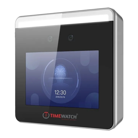
Appearance and Dimension:
White Light
Camera Camera
120 mm
Screen
Note:
The figures are for reference only.
Red
Black
Yellow
Blue
Black
Orange
Green
(COM)
Electric Dropbolt
Grey
(NO)
Power
White
Purple
Black
Black
Exit Button
23 mm
microUSB
Interface
Tamper
Network Interface
Wiring Terminal
Debugging Port
Door
Contact
(Sensor)
Advertisement
Table of Contents

Subscribe to Our Youtube Channel
Related Manuals for Timewatch ULTraFace 331


Summary of Contents for Timewatch ULTraFace 331
- Page 1 The installa on height here is the recommended height. You can change it according to your actual needs. For easy installa on, drill holes on moun ng surface according to the supplied moun ng template. You should purchase the gang box separately. ULTraFace 331 Face Time A endance Terminal Tamper...
- Page 2 Activation Activate via Device Set Applica on Mode Set Administrator Steps: Power on and wire the network cable a er installa on. You A er ac va on, you should select an applica on mode. 1. Enter the administrator’s name and tap Next. should ac vate the device before the first login.
Need help?
Do you have a question about the ULTraFace 331 and is the answer not in the manual?
Questions and answers