Table of Contents
Advertisement
Quick Links
Advertisement
Table of Contents

Related Manuals for Spectrum Digital TMS320DM368

Summary of Contents for Spectrum Digital TMS320DM368
- Page 1 TMS320DM368 Evaluation Module Technical Reference 2011 DSP Development Systems...
- Page 3 TMS320DM368 Evaluation Module Technical Reference 514565-0001 Rev. B March 2011 SPECTRUM DIGITAL, INC. 12502 Exchange Drive, Suite 440 Stafford, TX. 77477 Tel: 281.494.4505 Fax: 281.494.5310 sales@spectrumdigital.com www.spectrumdigital.com...
- Page 4 IMPORTANT NOTICE Spectrum Digital, Inc. reserves the right to make changes to its products or to discontinue any product or service without notice. Customers are advised to obtain the latest version of relevant information to verify that the data being relied on is current before placing orders.
- Page 5 Contents Introduction to the DM368 Evaluation Module ....... . Provides you with a description of the DM368 Evaluation Module, key features, and block diagram.
- Page 6 2.1.1.2.23 Register 720, CCD Internal I/O Direction Register 1 ....2-18 2.1.1.2.24 Register 721, CCS Internal I/O Read/Write Register 1 ....2-19 2.1.1.2.25 Register 722, CCD Internal I/O Direction Register 2 .
- Page 7 3.2.22 J23, I/O Interface Header ..........3-19 3.2.23 J24, DILC Host Connector .
- Page 8 About This Manual This document describes the board level operations of the DM368 Evaluation Module (EVM). The EVM is based on the Texas Instruments TMS320DM368 Processor. The DM368 Evaluation Module is a table top card that allows engineers and software developers to evaluate certain characteristics of the DM368 processor to determine if the processor meets the designers application requirements.
- Page 9 Related Documents, Application Notes and User Guides Information regarding the TMS320DM368 can be found at the following Texas Instruments website: http://www.ti.com Table 1: Manual History Revision History Beta Release Edits to CPLD registers, Tables Table 2: Board History History Revision...
- Page 11 Chapter 1 Introduction to the DM368 EVM Chapter One provides a description of the DM368 EVM along with the key features and a block diagram of the circuit board. Topic Page Key Features Functional Overview of the DM368 EVM Basic Operation Memory Map Boot / Configuration Switch Settings Power Supply...
- Page 12 1.1 Key Features The DM368 EVM is a standalone development platform that enables users to evaluate and develop applications for the TMS320DM368 processor. Schematics, logic equations and application notes are available to ease hardware development and reduce time to market.
- Page 13 Spectrum Digital, Inc • UART Interface • SD/MMC/MS, MMC/SD Media Card Interfaces • 2 Gigabytes NAND Flash • 128 Megabytes of One NAND • AIC3101 stereo codec • USB2 Interface • 10/100 MBS RMII Ethernet Interface • SPI EEPROM • IR Remote Interface via MSP430 •...
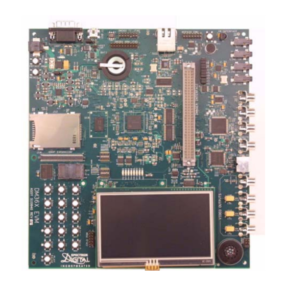
- Page 14 Spectrum Digital, Inc The two figures below show the DM368 EVM without the display and with the display mounted. Figure 1-2, DM368 EVM Without DM368 UIM Figure 1-3, DM368 EVM With DM368 UIM DM368 EVM Technical Reference...
- Page 15 Spectrum Digital, Inc 1.2 Functional Overview of the DM368 EVM The DM368 on the EVM interfaces to on-board peripherals through the 8/16-bit wide Async EMIF peripheral interface pins. The DDR2 memory is connected to its own dedicated 16 bit wide bus. The Async EMIF bus is also connected to the NAND and One NAND flash.
- Page 16 Spectrum Digital, Inc 1.4 Memory Map The DM368 processor has a byte addressable address space. There are some limitations to byte addressing which are determined by peripheral interconnection to the DM368 device. Program code and data can be placed anywhere in the unified address space.
- Page 17 Spectrum Digital, Inc Shown below is a break out of the memory spaces. Memory Space Address 0x02000000 NAND Chip Select 0 / One NAND 0x02004000 NAND Chip Select 1 0x40000000 CPLD Control Registers Figure 1-5, DM368 EVM Chip Enable Memory Space 1.5 Boot / Configuration Switch Settings...
- Page 18 Spectrum Digital, Inc 1.6 Power Supply The EVM operates from a single +5V external power supply connected to the main power input (J7), a 2.5 MM. barrel-type plug. Internally, the +5V input is converted into +1.2 to 1.35V, +1.8V and +3.3V using Texas Instruments TPS65530 power management IC and various linear regulators.
- Page 19 Spectrum Digital, Inc 1.7.1 DM368 UIM Installation on DM368 EVM Checklist To install the DM368 UIM on the DM368 EVM execute the following checklist: Turn off the power to your DM368 EVM ! Align connectors J1, J2, and J6 of the UIM with connectors J18, J19,and J23 on the DM368 EVM.
- Page 20 Spectrum Digital, Inc 1.7.2 Removal of UIM from the DM368 EVM Checklist To remove the UIM from the DM368 EVM execute the following checklist: Turn off the power to your DM368 EVM ! Carefully lift the edges of the UIM circuit board up. If necessary rotate lifting from right side, bottom edge, left side, right side, ..
- Page 21 Chapter 2 Board Components This chapter describes the operation of the major board components on the DM368 EVM. Topic Page Asychronous EMIF Interface 2.1.1 NAND Flash 2.1.1.1 One NAND 2.1.1.2 CPLD Interface 2.1.1.2.1 Register 0, CPLD Version 2.1.1.2.2 Register 1, Test Register 2.1.1.2.3 Register 2, LED Register 2.1.1.2.4 Register 3, Board Mux Control Register 2.1.1.2.5 Register 4, Board Switch Register...
- Page 22 Spectrum Digital, Inc Topic Page 2.1.1.3 Key Pad Interface 2-21 2.1.2 DDR2 Memory Interface 2-22 2.1.3 Media Card Interface 2-22 2.1.4 UART Interface 2-22 2.1.5 USB Interface 2-22 Input Video Port/Imager Input Port Interfaces 2-23 2.2.1 On Chip Video Output DAC 2-23 2.2.2...
- Page 23 Spectrum Digital, Inc 2.1 Asynchronous EMIF Interface An asynchronous 16 bit EMIF with two chip enables divide up the address space and allow for asynchronous accesses on the EVM. This interface connects to the NAND, One NAND, and CPLD registers on the EVM board.
- Page 24 Spectrum Digital, Inc 2.1.1.2 CPLD Interface The DM368 incorporates an Altera EPM2210, 256 Ball Grid Array (BGA) CPLD. The CPLD incorporates a number of internal registers, glue logic, and I/O multiplexing to allow for a very flexible development platform. The CPLD is accessed via EMIF CE1.
- Page 25 Spectrum Digital, Inc The following sections describe the registers and their function. A list of the registers is shown in the table below. Table 1: CPLD Registers Entire Address Address Reg # Function Address A13-A8 A2-A1 0x0400 0000 0 0 0 0 0 0...
- Page 26 Spectrum Digital, Inc 2.1.1.2.1 Register 0, CPLD Version This read only, 8 bit register, contains the 4 bit board type and the 4 bit CPLD version for version control. The default value is 0x21 for the DM368 EVM. 2.1.1.2.2 Register 1, Test Register This read only, 8 bit register, has a default value of 0xA5 and can be read and written to test the memory interface.
- Page 27 Spectrum Digital, Inc 2.1.1.2.5 Register 4, Board Switch Register This 8 bit, read only register mirrors the values set on switch SW5. These signals are shown in the table below. Table 3: Register 4, Board Switch Register Bit # SW5 Position...
- Page 28 Spectrum Digital, Inc 2.1.1.2.7 Register 6, GPIO Video Register Register 6 is a 8 bit, read/write register that controls the mapping of GPIO30/32/33, VDIN_WE, DRV_BUS. The default data value is 0b00000000. These controls are shown in the table below. Table 5: Register 6, GPIO Video Register...
- Page 29 Spectrum Digital, Inc 2.1.1.2.8 Register 7, Media Card Status Register 7 is a 8 bit, read only register that reads the “Insert” and “Write Protect” status of media cards. These functions of these bits are shown in the table below.
- Page 30 Spectrum Digital, Inc 2.1.1.2.10 Register 9, DILC Input Pin Mapping Register 9 is a 8 bit, read only register that maps DILC pins to read contents on this register. The mapping of these pins is shown in the table below.
-
Page 31: Table Of Contents
Spectrum Digital, Inc 2.1.1.2.12 Register 11, Internal I/O Mux Register 0 Register 11 is a 8 bit, read/write register that controls DM368 GPIO Muxing to IMAGER connector pin input. The default data is 0b00000000. The table below shows this muxing. -
Page 32: Bit # Muxing
Spectrum Digital, Inc 2.1.1.2.14 Register 13, Imager Internal I/O Direction Register 1 Register 13 is a 8 bit, read/write register that controls DM368 GPIO to IMAGER connector pin input/output mapping. The default data is 0b00000000. This mapping is shown in the table below. - Page 33 Spectrum Digital, Inc 2.1.1.2.16 Register 15, Imager Internal I/O Mux Register 3 Register 14 is a 8 bit, read/write register that controls DM368 GPIO Muxing to IMAGER connector pin input. The default data is 0b00000000. The table below shows this muxing.
-
Page 34: 0 = Gpio_Md1 Mux Selb
Spectrum Digital, Inc 2.1.1.2.18 Register 17, Imager Internal I/O Mux Register 4 Register 17 is a 8 bit, read/write register that controls DM368 GPIO Muxing to IMAGER connector pin input. The default data is 0b00000000. The table below shows this muxing. - Page 35 Spectrum Digital, Inc 2.1.1.2.20 Imager Multiplexer Mapping The CPLD GPIO functions are incorporated via CPLD control registers mapping selected CPLD/imager pins to DM368 GPIO. Each CPLD mapping function consists of 1 bit Direction control and 2 bits of multiplexer control. Most multiplexing has only 1 or 2 options, but the 2 bits in the multiplexing control were used to allow expansion of options for later revisions.
- Page 36 Spectrum Digital, Inc Table 18: Imager Multiplexer Mapping Requires CBT Requires CBT CPLD Imager Imager Imager-Mux selection over- selection over- Selection Selection IO Dir Bit Name ride (CPLD Reg ride (CPLD Reg (0)(1) (0)(1) and bit) and bit) None (OUTPUT)
- Page 37 Spectrum Digital, Inc 2.1.1.2.21 Register 19, Board RESET/EXTCLK Select Register Register 19 is a 8 bit, read/write register that allows the user to select reset to major external peripherals, and select an external clock for the DM368 EXT PIN (B19). The default data is 0b10000000.
- Page 38 Spectrum Digital, Inc 2.1.1.2.22 Register 20, Interrupt Select Register Register 20 is a 8 bit, read/write register that controls the interrupt source to GPIO0 of the DM368 processor. The default data is 0b00000000. The table below shows the mapping of these bits.
- Page 39 Spectrum Digital, Inc 2.1.1.2.24 Register 721, CCD Internal I/O Read/Write Register 1 Register 721 is a 8 bit, read/write register that controls CPLD GPIO input on read, and out value on write. The default data is 0b00000000. The table below shows the mapping of these bits.
- Page 40 Spectrum Digital, Inc 2.1.1.2.26 Register 723, CCD Internal I/O Read/Write Register 2 Register 723 is a 8 bit, read/write register that controls CPLD GPIO input on read, and out value on write. The default data is 0b00000000. The table below shows the mapping of these bits.
- Page 41 Spectrum Digital, Inc 2.1.1.2.28 Register 725, CCD Internal I/O Read/Write Register 3 Register 725 is a 8 bit, read/write register that controls CPLD GPIO input on read, and out value on write. The default data is 0b00000000. The table below shows the mapping of these bits.
- Page 42 Spectrum Digital, Inc 2.1.2 DDR2 Memory Interface The DM368 device incorporates a dedicated 16 bit wide DDR2 memory bus. The EVM uses a single 1 gigabit 16 bit wide memory on this bus, for a total of 128 megabytes of memory for program, data, and video storage.
- Page 43 Spectrum Digital, Inc 2.2 Input Video Port Interfaces/Imager Input Ports The DM368 EVM supports composite, component, or imager video capture. CBT multiplexers selected via CPLD registers chose the interface that is connected to the DM368 video input port. A Texas Instruments TVP5146 is used to decode composite video or S-video inputs into the device.
- Page 44 Spectrum Digital, Inc 2.3 AIC3101 Interface The EVM uses a Texas Instruments TLV320AIC3101 stereo codec for input and output of audio signals. The codec samples analog signals on the microphone or line inputs and converts them into digital data so it can be processed by the DSP. When the DSP is finished with the data it uses the codec to convert the samples back into analog signals on the line output so the user can hear the output.
- Page 45 Spectrum Digital, Inc 2.4 On Chip Voice Codec The DM368 integrates a single channel voice codec. The input for this codec is connected to on board microphone M1. The output of this codec is connected to on board speaker SPK1.
- Page 46 Spectrum Digital, Inc 2.7 Ethernet Interface The DM368 incorporates an internal MII ethernet MAC which interfaces to a Mircel 10/100 ethernet Phy. The 10/100 Mbit interface is isolated and brought out to a RJ-45 standard ethernet connector, P2. The ethernet address is stored in the on board C EEPROM manufacturing.
- Page 47 Spectrum Digital, Inc 2.8.1 MSP430 The DM368 EVM incorporates infrared remote, interface using a MSP430 microcontroller. The I C interface is used on the DM368 processor to communicate to the MSP430. The MSP430 acts as a slave device on the I C bus.
- Page 48 Spectrum Digital, Inc 2.11 Battery The DM368 EVM incorporates a battery holder to provide backup power to the internal real time clock when the power is not applied to the board. The optional battery should be +3 volt 20 millimeter coin type Lithium single cell.
- Page 49 Chapter 3 Physical Description This chapter describes the physical layout of the DM368 EVM and its interfaces. Topic Page Board Layout Connectors 3.2.1 J1, USB MiniAB Connector and Jumpers 3.2.2 J2, 14 Pin External JTAG Connector 3.2.3 J3, MSP430 JTAG Header 3.2.4 J4, Spare Jumper Holder 3.2.5...
- Page 50 Spectrum Digital, Inc Topic Page 3.2.29 P4, Line In 3-24 3.2.30 P5, Line Out 3-25 3.2.31 P6, Headphone Out 3-25 3.2.32 U1, Infrared Interface 3-26 3.2.33 SPK1, Speaker Interface 3-26 3.2.34 BHT1, Battery Interface 3-27 3.2.35 M1, Microphone Interface 3-27...
- Page 51 Spectrum Digital, Inc 3.1 Board Layout The DM368 EVM is a 8.0 x 8.7 inch (203 x 221 mm.) ten (10) layer printed circuit board which is powered by an external +5 volt only power supply. Figure 3-1 shows the layout of the top side of the DM368 EVM.
- Page 52 Spectrum Digital, Inc Figure 3-2 shows the layout of the bottom side of the DM368 EVM. Figure 3-2, DM368 EVM, Interfaces Bottom Side DM368 EVM Technical Reference...
- Page 53 Spectrum Digital, Inc 3.2 Connectors The DM368 EVM has numerous connectors, option jumpers, and interfaces to control and provide connections to various peripherals. These connectors and jumpers are described in the following sections. Table 1: DM368 Connectors Schematic Connector Size...
- Page 54 Spectrum Digital, Inc 3.2.1 J1, USB MiniAB Connector and Jumpers Connector J1 is a mini A/B USB connector. The pinout for the J1 connector is shown in the table below. Table 2: J1, MiniAB USB Connector Pins Signal USB_VBUS_CONN USB_DM...
- Page 55 Spectrum Digital, Inc 3.2.2 J2, 14 Pin External JTAG Connector Connector J2 is a 2 x 7 double row male header with pin 6 clipped to serve as a key. This is the standard interface used by JTAG emulators to interface to Texas Instruments processors.
- Page 56 Spectrum Digital, Inc 3.2.3 J3, MSP430 JTAG Header The J3, MSP430 JTAG header, is located on the top side of the board and is used to provide a programming interface to the MSP430 microcontroller. The pinout for the J3 connector is shown in the table below. This connector is typically used for factory use only.
- Page 57 Spectrum Digital, Inc 3.2.5 J5, 20 Pin ARM JTAG Emulation Header The J5 emulation header is located on the top side of the board and is used to provide an interface to ARM compatible JTAG emulators. The pinout for this connector is shown in the table below.
- Page 58 Spectrum Digital, Inc 3.2.7 J7, +5 Volts Input Connector J7 is the input power connector. This connector brings in +5 volts to the EVM. This is a 2.5mm. jack. The inside of the jack is tied to through a fuse to VCC_5V.
- Page 59 Spectrum Digital, Inc 3.2.9 J10, Imager Interface Connector J10 is 32 x 3 connector used to interface to external imager logic. The pin out for this connector is shown in the table below. Table 8: J10, Imager Interface Signal Signal...
- Page 60 Spectrum Digital, Inc 3.2.10 J14, EMIF/UPI DC Interface Table 9: J14, EMIF/UPI DC Interface Signal Signal Ground Ground EM_D0 EM_D1 EM_D2 EM_D3 EM_D4 EM_D5 EM_D6 EM_D7 Ground Ground EM_D8 EM_D9 EM_D10 EM_D11 EM_D12 EM_D13 EM_D14 EM_D15 Ground Ground EM_WAIT EM_CLK...
- Page 61 Spectrum Digital, Inc 3.2.11 J8, Y Component Video In, RCA Jack (Green) J8 is an RCA jack used as a Y component input to the THS7353, U15, pin 3. The figure below shows this connector as viewed from the card edge.
- Page 62 Spectrum Digital, Inc 3.2.13 J11, Pr Component Video In, RCA Jack (Red) J11 is an RCA jack used as a Pr component input to the THS7353, U15, pin 2. The figure below shows this connector as viewed from the card edge.
- Page 63 Spectrum Digital, Inc 3.2.15 J13, CVBS/Y Input, RCA Jack (Yellow) J13 is an RCA jack used as the CVBS/Y input to the TVP5146. The figure below shows this connector as viewed from the card edge. Pin 1,3,4 Shield (ground) Pin 2, Signal Input...
- Page 64 Spectrum Digital, Inc 3.2.17 J17, Y Component Video Out, RCA Jack (Green) J17 is an RCA jack used as a green component output from the THS7303 DAC, U23, pin 17, signal CH2-OUT. The figure below shows this connector as viewed from the card edge.
- Page 65 Spectrum Digital, Inc 3.2.19 J21, Pr Component Video Output, RCA Jack (Red) J21 is an RCA jack used as a Pr component output from the THS7303 DAC, U23, pin 19, signal CH1-OUT. The figure below shows this connector as viewed from the card edge.
- Page 66 Spectrum Digital, Inc 3.2.20 J18, J19, Video Output DC Connectors J18 and J19 make up the interface to the video output DC interface. The signals on each of these connectors are shown in the tables below. Table 19: J18, Video Output DC...
- Page 67 Spectrum Digital, Inc 3.2.21 J22, CPLD Programming Header The J22, CPLD programming header, is for use by the factory. This header is not intended to be used outside the factory. The signals on this header are shown in the table below.
- Page 68 Spectrum Digital, Inc 3.2.23 J24, DILC Host Connector J24 is the DILC Host Connector. The signals on this connector are shown in the table below. Table 23: J24, DILC Host Connector Pins Signal CAM_PWR CAM_PWR SPI2_SCLK_DILC Ground SPI2_SDO_DILC Ground SPI2_SDI_DILC...
- Page 69 Spectrum Digital, Inc 3.2.24 J25, MMC/SD Connector The J25 MMC/SD connector is located on the bottom side of the board and is used to provide an interface to a MMC/SD card. The pinout for the J25 connector is shown in the table below.
- Page 70 Spectrum Digital, Inc 3.2.26 P1, RS-232 UART The P1 connector is a 9 pin male D-connector which provides a UART interface to the EVM. This connector interfaces to the MAX 3221 RS-232 line driver (U3) and is located on the top side of the board. A view of the connector from the card edge is shown in the figure below.
- Page 71 Spectrum Digital, Inc 3.2.27 P2, Ethernet Interface The P2 connector is located on the top side of the board and is used to provide an Ethernet interface. P2 integrates the magnetics and standard RJ-45 connector. The two tables below show the signals present on the magnetics interface and the connector side.
- Page 72 Spectrum Digital, Inc 3.2.28 P3, Microphone In The microphone input, P3, is a 3.5 mm. stereo jack. Both inputs are connected to the microphone so it is monaural. The signal is connected to signals “MIC2R” and “MIC2L” of the TVL320AIC3101. The signals on the plug are shown in the figure below.
- Page 73 Spectrum Digital, Inc 3.2.30 P5, Line Out The connector P5, is an audio stereo output from the TVL320AIC3101, U7, on the EVM. The output connector is a 3.5 mm stereo jack. The signals on the mating plug are shown in the figure below.
- Page 74 Spectrum Digital, Inc 3.2.32 U1, Infrared Interface U1 is an infrared receiver mounted on the edge of the board. This device interfaces to the MSP430 mircrocontroller. The view of U1 is shown from a board edge view in the figure below.
- Page 75 Spectrum Digital, Inc 3.2.34 BHT1, Battery Interface BHT1 is a holder for a BA2032SM battery. The signals on each pin are shown below in the table below. Table 34: BHT1, Battery Interface BHT1 Pin # BHT1 Connection VBK, U9, Pin 13 Ground 3.2.35 M1, Microphone Interface...
- Page 76 Spectrum Digital, Inc 3.3 LEDs The EVM has nine (9) LEDs which are located on the top side of the board. Information regarding the LEDs are shown in the table below. Table 36: LEDs Schematic LED # Color Page +5 Volts present...
- Page 77 Spectrum Digital, Inc 3.4 Switches The EVM has twenty-three (23) switches. The function of these switches are shown in the table below. Table 37: Switches Schematic Switch Function Type Silkscreen Page EMU0/EMU1 Control 2 Position DIP PRTSC ON Push Button/Momentary...
- Page 78 SW1 is a 2 position DIP switch providing 4 options in selecting the state of the EMU0 and EMU1 pins on the TMS320DM368 processor. A view of the switch is shown in the figure below. The selection options with this switch are in the table below.
- Page 79 Spectrum Digital, Inc 3.4.4 SW4, Boot Mode / Configuration Select Switch SW4 is a 6 position DIP switch used to select the ARM Boot Mode and processor configuration. The first 3 positions selection the ARM boot mode. The last 3 positions select the processor configuration. The figure and tables below show these options.
- Page 80 Spectrum Digital, Inc 3.4.5 SW5, Board Configuration Select Switch SW5 is a 6 position switch that configures specific board functions. The figure below shows the switch as it appears on the EVM. NAND /ONE NAND EXTRA1 EXTRA2 EXTRA3 VCORE ADJUST...
- Page 81 Spectrum Digital, Inc 3.4.6 SW6 - SW21, Function Pushbuttons Switches SW6 through SW21 are push button momentary switches that are inputs in to the DM368 processor. These switches can be read with software and their function is determined by the application.
- Page 82 Spectrum Digital, Inc 3.5 Jumpers The following section describes the jumpers on the DM368 EVM. 3.5.1 JP1, Jumper Block Jumper block JP1, found on schematic page 39, allows the user to connect signals from the DM368 processor to the TVL320AIC3101, U7. The signals on this 9 x 2 header are shown in the table below.
- Page 83 Spectrum Digital, Inc 3.5.4 J26, USB ID Select The J26 jumper is used to pull the USB_ID line on USB connector high or low. The selections are shown below. Pos 1-2 View Pos 2-3 View Figure 3-26, J26, USB ID Select...
- Page 84 Spectrum Digital, Inc 3.6 Test Points The EVM has 65 test points. The following 2 figures identify the position of each test point. The next two tables lists each test point and the signal appearing on that test point. TP11-TP16...
- Page 85 Spectrum Digital, Inc TP53,TP54 Figure 3-29, DM368 EVM, Bottom Side Test Points 3-37...
- Page 86 Spectrum Digital, Inc Table 46: DM368 EVM Test Points Schematic Schematic TP # Signal TP # Page Page TP46 U33A, F2, B1.IO_21 TP47 U33D, P11, B4.IO_47 VCC_5V TP48 U33D, P7, B4.IO_21 U2, Pin 6, MP430_IO2 TP49 U33A, M4, B1.IO_58 U5, Pin 25, INT#PHYAD0 TP50 U33A, P2, B1.IO_65...
- Page 87 Spectrum Digital, Inc There are 18 power test points on the EVM. These test points provide a convenient mechanism to check the EVM’s multiple power supplies. The table below shows the voltages for each test point and what the supply is used for.
- Page 88 Spectrum Digital, Inc DM368 EVM Technical Reference 3-40...
- Page 89 Appendix A Schematics This appendix contains the schematics for the DM368 EVM.
- Page 90 Spectrum Digital, Inc DM368 EVM Technical Reference...
- Page 91 Spectrum Digital, Inc...
- Page 92 Spectrum Digital, Inc DM368 EVM Technical Reference...
- Page 93 Spectrum Digital, Inc...
- Page 94 Spectrum Digital, Inc DM368 EVM Technical Reference...
- Page 95 Spectrum Digital, Inc...
- Page 96 Spectrum Digital, Inc DM368 EVM Technical Reference...
- Page 97 Spectrum Digital, Inc...
- Page 98 Spectrum Digital, Inc DM368 EVM Technical Reference A-10...
- Page 99 Spectrum Digital, Inc A-11...
- Page 100 Spectrum Digital, Inc DM368 EVM Technical Reference A-12...
- Page 101 Spectrum Digital, Inc A-13...
- Page 102 Spectrum Digital, Inc DM368 EVM Technical Reference A-14...
- Page 103 Spectrum Digital, Inc A-15...
- Page 104 Spectrum Digital, Inc DM368 EVM Technical Reference A-16...
- Page 105 Spectrum Digital, Inc A-17...
- Page 106 Spectrum Digital, Inc DM368 EVM Technical Reference A-18...
- Page 107 Spectrum Digital, Inc BLM21PG221SN1 A-19...
- Page 108 Spectrum Digital, Inc DM368 EVM Technical Reference A-20...
- Page 109 Spectrum Digital, Inc A-21...
- Page 110 Spectrum Digital, Inc DM368 EVM Technical Reference A-22...
- Page 111 Spectrum Digital, Inc A-23...
- Page 112 Spectrum Digital, Inc DM368 EVM Technical Reference A-24...
- Page 113 Spectrum Digital, Inc A-25...
- Page 114 Spectrum Digital, Inc DM368 EVM Technical Reference A-26...
- Page 115 Spectrum Digital, Inc A-27...
- Page 116 Spectrum Digital, Inc DM368 EVM Technical Reference A-28...
- Page 117 Spectrum Digital, Inc A-29...
- Page 118 Spectrum Digital, Inc DM368 EVM Technical Reference A-30...
- Page 119 Spectrum Digital, Inc A-31...
- Page 120 Spectrum Digital, Inc DM368 EVM Technical Reference A-32...
- Page 121 Spectrum Digital, Inc A-33...
- Page 122 Spectrum Digital, Inc DM368 EVM Technical Reference A-34...
- Page 123 Spectrum Digital, Inc A-35...
- Page 124 Spectrum Digital, Inc DM368 EVM Technical Reference A-36...
- Page 125 Spectrum Digital, Inc A-37...
- Page 126 Spectrum Digital, Inc DM368 EVM Technical Reference A-38...
- Page 127 Spectrum Digital, Inc A-39...
- Page 128 Spectrum Digital, Inc DM368 EVM Technical Reference A-40...
- Page 129 Spectrum Digital, Inc A-41...
- Page 130 Spectrum Digital, Inc DM368 EVM Technical Reference A-42...
- Page 131 Spectrum Digital, Inc A-43...
- Page 132 Spectrum Digital, Inc DM368 EVM Technical Reference A-44...
- Page 133 Spectrum Digital, Inc A-45...
- Page 134 Spectrum Digital, Inc DM368 EVM Technical Reference A-46...
- Page 135 Spectrum Digital, Inc A-47...
- Page 136 Spectrum Digital, Inc DM368 EVM Technical Reference A-48...
- Page 137 Spectrum Digital, Inc A-49...
- Page 138 Spectrum Digital, Inc DM368 EVM Technical Reference A-50...
- Page 139 Spectrum Digital, Inc A-51...
- Page 140 Spectrum Digital, Inc DM368 EVM Technical Reference A-52...
- Page 141 Spectrum Digital, Inc A-53...
- Page 142 Spectrum Digital, Inc DM368 EVM Technical Reference A-54...
- Page 143 Appendix B Mechanical Information This appendix contains the mechanical information about the DM368 EVM produced by Spectrum Digital.
- Page 144 Spectrum Digital, Inc DM368 EVM Technical Reference...
- Page 146 Printed in U.S.A., March 2011 514565-0001 Rev B...
Need help?
Do you have a question about the TMS320DM368 and is the answer not in the manual?
Questions and answers