
Related Manuals for Novatek-electro OM-310


Summary of Contents for Novatek-electro OM-310
- Page 1 NOVATEK-ELECTRO LTD Research-and-Manufacture Company POWER LIMITER OM-310 USERS MANUAL www.novatek-electro.com...
-
Page 2: Table Of Contents
1. DESCRIPTION AND OPERATION ............................ 3 1.1 APPLICATION ................................3 1.1.1 OM-310 power limiter is designed for the following applications: ................. 3 1.1.2 OM-310 application limitations and proper selection of parameters ..............3 1.1.3 Integrated relays output terminals specification ....................4 1.1.4 List of abbreviations used ............................. -
Page 3: Description And Operation
320A, the current transformer core saturation starts, and the measurement error increases rapidly. Regardless In spite of the actual current value, the current measured by OM-310 will not exceed 400A. Setting up certain pro- grammable parameters (maximum current protection) without regard to current transformers saturation will make protection tripping impossible. -
Page 4: Integrated Relays Output Terminals Specification
1.2.2 Measured and calculated parameters output to the display unit, their effective range limits and toler- ances are given below in Table 1.4. Note: The display device includes: - two pieces of three-digit, seven segment indicators on OM-310 front panel; NOVATEK-ELECTRO ОМ-310... - Page 5 - 5 - - PC, connected to one of OM-310 interfaces (MODBUS, RS-232). Table 1.4 - Measured and Displayed Parameters Measurement functions Range Accuracy Mnemonics Address Measurement units used at data transfer Currents 1/10 of an ampere* Phase currents RMS values, A...
-
Page 6: Programmable Parameters And Their Variability Ranges
4- relay will be switched on after ex- ceeding of main tripping Characterizing relay 0 – relay will close after expiration of time activation mode when 1 – relay will close after reduction of consumed wattage to level NOVATEK-ELECTRO ОМ-310... - Page 7 Voltage imbalance pro- 0- protection function prohibited tection function per- 1- protection function permitted, after- mission tripping automatic reset prohibited 2- protection function permitted, after- tripping automatic reset permitted Phase sequence pro- 0- protection function prohibited NOVATEK-ELECTRO ОМ-310...
- Page 8 parameters shall be used to prohibit AR in case of voltage faults Load relay operation 0 – manual load start from OM-310 permitted after OM de- front panel vice power-on 1- load start after AR delay time load start after 2 sec delay ...
-
Page 9: Operating Controls And The Dimensions Of The Ом-310
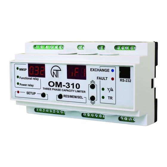
10 – green LED - glows when the ОМ-310 characterizing relay works in the mode of controlling additional load (par. 2.4.3) 11 – green LED - TR glows when the ОМ-310 characterizing relay functions in the time relay mode and blinking when OM-310 is working in signalization mode of main tripping exceeding of active power. NOVATEK-ELECTRO... -
Page 10: Power Limiting Functions
15 - SETUP button engages the parameter setup mode Figure 1.1 - OM-310 device controls and dimensions N o t e 1 - In order to enhance the ОМ-310 reliability, for the mains voltage input, terminals with 7.5 mm spacing were used. - Page 11 - time, during which the load relay will be open after de-energizing resulting from the watts input crossing the main threshold Figure 1.2 - OM-310 operation in the power limiting mode when =0, =1, =3 1.2.5.3 Active power limiting during operation of a characterizing relay at = 2 ( relay used for connecting ad- ditional load) After ОМ-310 energizing, after AR time (Att parameter) the load relay will close.
-
Page 12: Protection Functions
“P2F” – additional load energizing threshold, %. 1.2.6 Protection functions 1.2.6.1 Protection types OM-310 device provides the following types of load protection: - maximum phase current; - against line-to-earth fault (based on zero sequence current): - for minimum line voltage;... -
Page 13: Product Package Contents
1.2.6.7 Starter unit operability control (at =1). If currrents are present when the relay is open, the starter is considered faulty. Further OM-310 operation is locked. The alarm reset can be performed by de-energizing only. 1.3 PRODUCT PACKAGE CONTENTS The product package contents are shown in Table 1.7. -
Page 14: Disabled Keypad Mode
MMSP is devised to ease the service personnel’s operations with ОМ-310. To employ MMSP mode in OM-310, the user needs to set =1 parameter, or perform resetting to factory set- tings. (2.2.4). When ОМ-310 unit is in this operation mode, green LED “MMSP” is on. -
Page 15: Restoring Factory Settings
When using other capacity loads, current transformers with 5A rated output current shall be connected in accor- dance with Fig 2.1. For correct OM-310 operation, the current transformers’ polarity must be observed. 2.3.2 Run all three power phase cables through differential current transformer (zero sequence transformer) and connect the DCT to ОМ-310. -
Page 16: Intended Use
- 16 - X1-1 X1-2 OM-310 Cont Designation Designation Cont АВ K2-nc 28.5 K2-com K2-no 31.5 K1-1-nc K1-1 K1-1-com K1-1-no B RS-485 K1-2-nc K1-2 A RS-485 K1-2-com K1-2-no Tdif_b Tdif_e Cont L3_OUT1 L2_OUT1 L1_OUT1 Designation cont TxD_rs232 RxD_rs232 GND_RS232 L3_OUT2... -
Page 17: Om-310 Operation Before Load Relay Closure
Communication between PC and ОМ-310 is effected through serial interface. The connection schematic is shown in fig. 2.2. Each ОМ-310 has a unique communication address. PC controls each OM recognizing them by their address. OM-310 can operate within RTU mode controlled Modbus networks. NOVATEK-ELECTRO ОМ-310... - Page 18 Command code 0x06, record – one word Using this command is not recommended as recording incorrest data may lead to ОМ-310 failure. Data recording is possible only to the programmable parameters addresses (Table 1.5), except for parameters listed in Table 2.3. NOVATEK-ELECTRO ОМ-310...
- Page 19 CRC CHK high 0x56 Command code 08h – diagnostics. 08h function provides a number of tests for checking communication system between PC and OM-310, and for OM-310 integrity control. The function uses the sub function field to specify the action performed (test).
- Page 20 Fault register 2 bit mapping shown in table 2.8 Fault log Fault code 1 fault code according to table 2.8 value of parameter 1 parameter value according to table 2.8 Fault time 1 two upper bytes two lower bytes NOVATEK-ELECTRO ОМ-310...
-
Page 21: The Load Energize/De-Energize Remote Control Via Rs-232/Rs-485 Interface
N o t e 1 - Fault time – is time period since the OM-310 power-on till the moment of the fault occurrence. Meas- ured in minutes. N o t e 2 - Upon ОМ-310 delivery, or after factory settings reset (2.2.6), error code 40 and parameter value 10000 are written in the log. -
Page 22: Load Energize/De-Energize Via Remote Breaker
Note. Time of fault is defined by OM internal clock. As ОМ-310 has no integral power source, the time when the device was de-energized, is not accounted. Number of synchronously stored fault codes is five. When next following faults occur, the information of this fault is recorded over the latest fault. To view log press RES/MEM/SEL button. NOVATEK-ELECTRO ОМ-310... -
Page 23: Load Start/Cutoff Control With Use Of Om-310 Front Panel
XXX - hours since fault YY - number of minutes since fault occurrence 2.4.9 Load start/cutoff control with use of OM-310 front panel Depending on the parameter value, the ОМ-310 load relay can be controlled by pressing buttons UP and DOWN simultaneously (unless ОМ-310 is in keypad lock-up mode):... -
Page 24: Maintenance
The ОМ-310 equipment service period is 10 years. Upon expiration of the equipment service period, please, contact the manufacturer. The manufacturer warrants defect-free performance of OM-310 device within three years after the date of sale provided that the following conditions have been met: - proper installation;... -
Page 25: Appendix 1- Dependent Time Delay Current Based Protection Types
- 25 - APPENDIX 1- Dependent time delay current based protection types: NOVATEK-ELECTRO ОМ-310... - Page 26 - 26 - NOVATEK-ELECTRO ОМ-310...
- Page 27 - 27 - NOVATEK-ELECTRO ОМ-310...
- Page 28 - 28 - NOVATEK-ELECTRO ОМ-310...
- Page 29 X-ON Electronics Largest Supplier of Electrical and Electronic Components Click to view similar products for category: General Purpose Relays Click to view products by manufacturer: Novatek Other Similar products are found below : APF30318 JVN1AF-4.5V-F PCN-105D3MHZ 5JO-10000S-SIL 5JO-1000CD-SIL 5JO-400CD-SIL LY2S-AC220/240 LYQ20DC12 6031007G 6131406HQ 6-1393099-3 6-1393099-8 6-1393122-4 6-1393123-2 6-1393767-1 6-1393843-7 6-1415012-1 6-1419102-2 6- 1423698-4 6-1608051-6 6-1608067-0 6-1616170-6 6-1616248-2 6-1616282-3 6-1616348-2 6-1616350-1 6-1616350-8 6-1616358-7 6- 1616359-9 6-1616360-9 6-1616931-6 6-1617039-1 6-1617052-1 6-1617090-2 6-1617090-5 6-1617347-5 6-1617353-3 6-1617801-8 6-...
Need help?
Do you have a question about the OM-310 and is the answer not in the manual?
Questions and answers