Table of Contents
Advertisement
Quick Links
ST-72 User's Manual
Document: UM-1007
Revision Level A
INSTRUCTION MANUAL
R.C. SYSTEMS CO. INC.
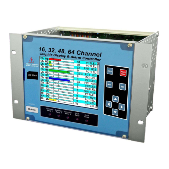
MODEL ST-72 16,32,48 or 64 CHANNEL CONTROLLER
(Firmware 2.0 & later)
Warning: Read & understand contents of this manual prior to
operation. Failure to do so could result in serious injury or death.
PHONE: (409)986-9800 FAX: (409) 986-9880
8621 HWY 6 HITCHCOCK, TX 77563
Website:
http://www.rcsystemsco.com
0
Advertisement
Chapters
Table of Contents

Related Manuals for RC Systems ST-72


Summary of Contents for RC Systems ST-72
- Page 1 Revision Level A INSTRUCTION MANUAL R.C. SYSTEMS CO. INC. MODEL ST-72 16,32,48 or 64 CHANNEL CONTROLLER (Firmware 2.0 & later) Warning: Read & understand contents of this manual prior to operation. Failure to do so could result in serious injury or death.
- Page 2 ST-72 User's Manual Document: UM-1007 Revision Level A SECTION 1 GENERAL DESCRIPTION ............. 1 IMPORTANT SAFETY ISSUES ................. 1 GENERAL DESCRIPTION................. 2 DATA DISPLAY SCREENS ................3 1.3.1 MAIN DATA SCREEN 1.3.2 24 HOUR TREND SCREEN 1.3.3 BAR GRAPHS SCREEN 1.3.4...
- Page 3 ST-72 User's Manual Document: UM-1007 Revision Level A 2.4.2.5 HORN ON 2.4.2.6 COLOR 2.4.2.7 ENABLED 2.4.3 FAULT ALARM MENU 2.4.4 DATA FROM MENU TO SET INPUT SOURCE 2.4.4.1 SOURCE 2.4.4.2 MIN RAW & MAX RAW 2.4.4.3 FILTER SAMPLE COUNT 2.4.4.4 LOCAL CAL 2.4.4.5...
- Page 4 ST-72 User's Manual Document: UM-1007 Revision Level A 2.5.3.4 NETMASK 2.5.3.5 GATEWAY 2.5.4 TROUBLESHOOTING 2.5.4.1 VIEW COMM FAILURES 2.5.4.2 CLEAR FAILURE COUNTS SECURITY MENU .................... 44 2.6.1 USER NAME 2.6.2 LOCK CODE 2.6.3 MODBUS LOCK CODE SYSTEM MENU ....................45 2.7.1...
- Page 5 ST-72N4 NEMA 4X LARGE WALL MOUNT FIBERGLASS ENCLOSURE ..99 ST-72CP NEMA 4X COMPACT WALL MOUNT FIBERGLASS ENCLOSURE ST-72XP NEMA 7 WALL MOUNT ALUMINUM ENCLOSURE ...... 102 ST-72 MAIN I/O & OPTION PCB FOOTPRINT DIMENSIONS AND ENCLOSURE CAPACITIES ..................103 SECTION 7 WIRELESS OPTION ..............105 RADIO SETUP MENU ...................
- Page 6 SECTION 10 NETWORK CONNECTION ............127 10.1 DIRECT CONNECTION WITH CROSSOVER CABLE OR HUB/SWITCH ..127 10.2 CONNECTING THE ST-72 TO AN EXISTING LAN ........128 10.3 CONNECTING THE ST-72 ON AN ISOLATED NETWORK ......129 10.4 STATIC IP CONFIGURATION ............... 130 10.4.1 ST-72 STATIC IP CONFIGURATIION...
- Page 7 ST-72 User's Manual Document: UM-1007 Revision Level A GENERAL DESCRIPTION SECTION 1 1.1 IMPORTANT SAFETY ISSUES The following symbols are used in this manual to alert the user of important instrument operating issues: This symbol is intended to alert the user to the presence of important operating and maintenance (servicing) instructions.
- Page 8 Revision Level A 1.2 GENERAL DESCRIPTION The R. C. Systems Co. Inc. ST-72 64 channel Controller is designed to display and control alarm event switching for up to 64 sensor data points. It may also be set as a 16, 32 or 48 channel controller for applications needing fewer inputs.
- Page 9 1.3.1 MAIN DATA SCREEN The ST-72 Main Data screen shown below (Figure1-1) displays all active channels at once. It is capable of displaying 16, 32, 48 or 64 channels depending on the controller’s configuration. This screen displays measurement name and uses a bar graph and...
- Page 10 ST-72 User's Manual Document: UM-1007 Revision Level A have been acknowledged by an operator the cell will remain the appropriate color but will stop flashing, showing the alarm has been acknowledged. Utilizing the Display Alarm feature in the Systems Configuration menu allows new alarms to always force the LCD to the Main Data screen.
- Page 11 1.3.2 24 HOUR TREND SCREEN The ST-72 24 Hour Trend screen shown in Figure 1-3 displays a 24 hour trend of input data for the channel selected. Vertical tic marks are each hour and horizontal tic marks are each 10% of full scale. Colored lines indicate alarm levels. The alarm level lines have triangles on the right end that indicate high and low trip for each alarm level.
- Page 12 1.3.3 BAR GRAPHS SCREEN The ST-72 Bar Graphs screen shown in Figure 1-4 allows 16 channels to be viewed simultaneously. Both engineering units and bar graph values are indicated in real time. Lines across the bars indicate the alarm trip points making it easy to identify channels near alarm.
- Page 13 1.3.4 COMBINATION SCREEN The ST-72 Combination screen shown in Figure 1-5 offers a view of a single channel but displays the data as a 30 minute trend, bar graph and large engineering units. The bar graph and the background color changes and flashes indicating alarm condition. Once the alarm is acknowledged they stop flashing.
- Page 14 1.3.5 ZONE SCREEN The ST-72 Zone screen displays the eight possible zones simultaneously. If an alarm condition occurs the user will be able to quickly see in what zone the situation is occurring. Each active zone is divided into alarm levels which are green until an alarm is present.
- Page 15 *220-240VAC @ 5A max * Universal AC input automatically selects AC input range. The 600 watt power supply (Figure 3-7) is for powering the ST-72 and up to 64 detectors. This power supply can be paralleled with up to three additional 600 watt power supplies providing up to 2400 watts for applications with large power requirements.
- Page 16 Revision Level A *220-240VAC @ 1.6A max * A slide switch on the front of the power supply selects AC input range. The 10-0172 150 watt power supply (Figure 3-7) is for powering the ST-72 and up to 64 detectors. 1.4.1.3 RELAYS The ST-72 comes standard with five Standard SPDT 5A relays, consisting of one dedicated HORN and one dedicated FAULT relay plus 3 programmable alarm relays.
- Page 17 ST-72 User's Manual Document: UM-1007 Revision Level A magnetic keys. This option is included as a standard feature. It is useful in applications where it may be inconvenient to open the enclosure’s door to access the touch keypad. 1.4.7 APPROVALS C22.2 No.
- Page 18 Next Trend and Combination screens with switches between the 5 graphic data screens. When ST-72 power is applied, the graphic LCD starts in the Main Data screen. 2.1 MAIN MENU CONFIGURATION Variables inside Main menu tree allow optimum ST-72 configuration for a wide range of demanding multi-point monitoring applications.
- Page 19 ST-72 User's Manual Document: UM-1007 Revision Level A Standard Relay A1 Votes Required A2 Votes Required A3 Votes Required Acknowledge Failsafe Zone 1 Override 1 Channel Standard Relay Menus are Identical Horn/Piezo Alarm 1 Beep Alarm 2 Alarm 3 Alarm Outputs...
- Page 20 ST-72 User's Manual Document: UM-1007 Revision Level A Figure 2-1 Ch. 38 Alarm 1 SetPoint Latching Trip On High On Delay (sec) Off Delay (min) Horn Drive Ch. 38 Alarm 2 SetPoint Latching Trip On High On Delay (sec) Off Delay (min)
- Page 21 ST-72 User's Manual Document: UM-1007 Revision Level A Ch. 38 Alarm 1 SetPoint Latching Trip On High On Delay (sec) Off Delay (min) Horn Drive Ch. 38 Alarm 2 SetPoint Latching Trip On High On Delay (sec) Off Delay (min)
- Page 22 ST-72 User's Manual Document: UM-1007 Revision Level A Configure Name Controller 1 Contrast Date 10/20/2010 Time 09:43:28 Enable Channel Count Display Alarm Main Data Warmup Time Cal Purge Time (min) Zone Screen Enabled Block Negative Zone Names Zone 1 North Entrance...
- Page 23 ST-72 User's Manual Document: UM-1007 Revision Level A Figure 2-4 Standard Relay Standard Relay 1 Standard Relay 2 Standard Relay 3 Fault Relay Horn Relay Discrete Relay Discrete Relay Ch.01-16 Discrete Relay Ch.01-16 Alarm 1 Discrete Relay Ch.17-32 Alarm 2 Discrete Relay Ch.33-48...
- Page 24 ST-72 User's Manual Document: UM-1007 Revision Level A Discrete Relay Ch.01-16 Alarm 1 Alarm 1 Ch.01 Alarm 1 Alarm 2 Ch.02 Alarm 1 Alarm 3 Ch.03 Alarm 1 Fault Ch.04 Alarm 1 Ch.05 Alarm 1 " " " " Ch.16 Alarm 1...
- Page 25 ST-72 User's Manual Document: UM-1007 Revision Level A See Figure 2-5 Piezo Beep Test. Press "Next" To Exit. BEEP! LED Blink Test. Press "Next" To Exit. Diagnostics Standard Relays Discrete Relays Programmable Relays Analog Inputs See Figure 2-1 Analog outputs...
- Page 26 The menu item identified as ALARM OUTPUTS is accesses through the Main Menu. Selecting it allows users to configure the different types of outputs that can be connected to the ST-72 controller through the menu shown in Figure 2-8. The variables under this menu are STANDARD RELAY 1, STANDARD RELAY 2, STANDARD RELAY 3, HORN/PIEZO, DISCRETE RELAY, and PROGRAMMABLE RELAY BOARD.
- Page 27 ST-72 User's Manual Document: UM-1007 Revision Level A Standard Relay A1 Votes Required A2 Votes Required A3 Votes Required Acknowledge Failsafe Zone 1 Override 1 Channel Standard Relay and Programmable Relay Menus are Identical Horn/Piezo Alarm Outputs Alarm 1 Beep...
- Page 28 2.3.1 STANDARD RELAY 1, 2, AND 3 Every ST-72 comes standard with three programmable relays that the user can individually program to suit their needs. This is achieved through the STANDARD RELAY menus accessed from the ALARM OUTPUTS menu. Only one Standard Relay menu screen is shown in Figure 2-9 because all the standard relay’s menus are...
- Page 29 Some applications have different types of sensors, or sensors in different areas connected to the same ST-72 Controller. In these cases, it may be undesirable for a sensor in one area to trip the same relay as a sensor in another area. The Zone menus may restrict this.
- Page 30 ST-72 User's Manual Document: UM-1007 Revision Level A 2.3.2.1 A1 A2 & A3 Alarm 1, Alarm 2, & Alarm 3 menus control how this alarm level from each channel will affect the standard horn relay. Choices are OFF, ON or BEEP (one Hz. Pulsating).
- Page 31 ST-72 User's Manual Document: UM-1007 Revision Level A 2.3.4 PROGRAMMABLE RELAY The 10-0350 Programmable relay option board may be added if the user needs sixteen more programmable relays in addition to the three standard relays. These 16 relays are configured through the PROGRAMMABLE RELAY menus accessed from the ALARM OUTPUTS menu show in Figure 2-12.
-
Page 32: Table Of Contents
ST-72 User's Manual Document: UM-1007 Revision Level A 2.4.1 CHANNEL CONFIGURATION MENUS Once the appropriate channel has been selected its configuration menu allows the following parameters to be accessed: Alarm 1, Alarm 2, Alarm 3, Fault Alarm, Data From, Linearize, and Configure. -
Page 33: Channel 38 Config
ST-72 User's Manual Document: UM-1007 Revision Level A 2.4.2 ALARM 1 / ALARM 2 / ALARM 3 MENU The ALARM MENU parameters are listed only once, because alarms 1, 2, and 3 are identical except A1 does not have the option to change the color, it is always yellow, and only A3 can be turned off if not needed. -
Page 34: Fault Alarm
ST-72 User's Manual Document: UM-1007 Revision Level A 2.4.2.5 HORN ON The HORN ON entry allows linking this alarm to the common horn relay. NO causes the alarm to have no effect upon the horn relay. Entering YES causes this alarm to... -
Page 35: No Ch. 38 Fault Alarm Setpoint -10
ST-72 User's Manual Document: UM-1007 Revision Level A Modbus RS-485 from up to four configured master ports connected to Modbus slave devices. Modbus TCP/IP connected to the Ethernet port. Note: Each Modbus menu selection also requests the RTU # and the Alias register # location of the data to be retrieved from the RTU. - Page 36 Modbus® device with zero at 200 counts and 100% at 1000 counts, then this menu’s MIN should be set at 200 and MAX at 1000. If communicating with the ST-72’s optional 12 bit Analog Input PCB the MIN should be 800 and the MAX 4000.
- Page 37 Some transmitters or monitoring devices providing ST-72 inputs also indicate special modes of operation, such as Calibration, Maintenance or Fault, by transmitting a special <4mA or negative “Marker” value. The ST-72 offers channel Marker menus for detecting and indicating such events (see Figure 2-18). While active, the ST-72diplays a 6-digit ASCII message to indicate the special event and if equipped with 10-0348 4-20mA output option, the ST-72 also transmits the same <4mA value.
- Page 38 4.0mA = 0% and 5.0mA = 100% remaining sensor life. The ST-72 reads this value and records it as the channel’s Sensor Life. Sensor Life is stored in the ST-72 Modbus database and displayed as a bar-graph in the Sensor Info screen (see section 2.7.7).
- Page 39 ST-72 User's Manual Document: UM-1007 Revision Level A 2.4.4.7 ALIAS The Alias register numbers define the location of the variable representing the input value of the Modbus data received through the Communications ports. This number must be obtained from the manufacturer of the Modbus RTU device.
-
Page 40: 38 Linearize Input Output
ST-72 User's Manual Document: UM-1007 Revision Level A 2.4.5 LINEARIZE The linearization menu allows each channel to have its own linearization curve stored in the controller’s non-volatile memory. Input versus output points must be entered in percent of full scale values. This means if the range is 0-200 ppmH2S then 100 ppm is 50% of full scale. - Page 41 ST-72 User's Manual Document: UM-1007 Revision Level A 2.4.6.1 INFO / MEASUREMENT NAME The first two items in this menu are for entering the 16 character Measurement Name and 6 character engineering unit ASCII fields. Eunits should define the units of measure for what this channel is to display.
- Page 42 ST-72 User's Manual Document: UM-1007 Revision Level A be grouped together. Once the channels are assigned to a certain group relays can be configured to respond to only the channels in this ZONE (see section 2.3.1.4). 2.4.6.6 DEADBAND DEADBAND allows forcing low values to continue to read zero. This is useful when there are small amounts of background gases that cause fluctuating readouts above zero.
- Page 43 ST-72 User's Manual Document: UM-1007 Revision Level A Edit Once the correct com port is selected brings you to that com port’s configuration menu, shown on right below. Com ports 1-4 have identical menus and are shown only once. COM1 Settings...
-
Page 44: Communication Settings
When communication has switched to the redundant port the ST-72 trips the Fault relay, beeps, and displays a warning telling the user there has been a communication error. The user is able to... - Page 45 Manual test can be performed on the redundant or primary port by going into the redundant port’s com setting menu and selecting TEST REDUNDANT PORT or TEST PRIMARY PORT. While in this menu the ST-72 also gives the active port on the screen.
-
Page 46: Radio Setup
This option is only available if SYMPATHY ENABLED is set to YES. 2.5.1.6.3 A2 TRANSMIT When set to YES the ST-72 t broadcasts the alarm 2 alarm flag out of the communication port. This option is only available if SYMPATHY ENABLED is set to YES. 2.5.1.6.4... -
Page 47: Modbustcp Settings
2.5.2.3 MASTER POLL DELAY The time in milliseconds the unit will delay between Modbus master requests. 2.5.3 NETWORK SETTINGS section 10 for integrating a ST-72 into an Ethernet network. Communication Settings Network Settings COM1 Settings DHCP Enabled COM2 Settings... -
Page 48: Netmask
TROUBLESHOOTING The TROUBLESHOOTING option in the communication settings menu can prove to be very helpful when setting up communications through the ST-72’s numerous communication ports. This feature allows the user to see how many messages were either corrupt when received or not received at all. - Page 49 ST-72 User's Manual Document: UM-1007 Revision Level A 2.5.4.1 VIEW COMM FAILURES When VIEW COMM FAILURES is selected the screen in Figure 2-27 is shown. Each individual channel is shown and it is color coded by the communication port that it is...
- Page 50 To lock or unlock the system the correct 4 digit authorization number must be entered into the Lock Code field. The ST-72 will ask this 4 digit code to be re-entered and then it will be lock. Once locked, re-entering the code will unlock the unit.
- Page 51 The SYSTEM menu is accessed through the MAIN MENU. Some items needing configuration are not specific to a channel but affect the entire ST-72 system. These are located in the system entry menu shown in Figure 2-29. System menus are accessed by...
- Page 52 ST-72 User's Manual Document: UM-1007 Revision Level A Configure Name Controller 1 Contrast Date 10/20/2010 Time 09:43:28 Enable Channel Count Display Alarm Main Data Warmup Time (min) Cal Purge Time (min) Zone Screen Enabled Block Negative Relay Refresh (min) Zone Names...
- Page 53 ST-72 User's Manual Document: UM-1007 Revision Level A 2.7.1 VERSION The VERSION line in the System menu displays the version of firmware that is programmed in the controller. System Version v1.00 Configure Zone Names Mimic Mode SD Card View Event Log...
- Page 54 2.7.2.4 ENABLE CHANNEL COUNT For applications that do not need 64 channels, the ST-72 can be configured to display 16, 32, or 48. With fewer channels to be displayed in MAIN DATA screen the cells expand for better resolution.
- Page 55 2.7.4 MIMIC MODE When mimic mode is enabled, the ST-72 will duplicate the data and alarms of another ST-72 which can be connected with RS485 or TCP/IP. Entering the communications port and slave ID allows the ST-72 to automatically retrieve programmed configuration parameters from the Main controller.
- Page 56 2.7.5 SD CARD A two gigabyte SD card comes standard with each ST-72. This SD card is not needed for normal operation, but is useful for data logging and backing up configuration. When the data logger is enabled, every ten minutes the Min, Max, Average, Alarm 1/2/3 status, Fault status, Calibration status, and Alarm reset for each active channel is written to the SD card in one minute intervals.
- Page 57 2.7.5.4 LOAD CONFIGURATION FILE Once a file is backed up on the SD card it can be loaded back into the ST-72 to change the current configuration to a previous configuration or the SD card can be moved to another unit and the configuration can be copied to the second unit.
- Page 58 2.7.6 VIEW EVENT LOG The ST-72 logs the last 2000 events, first in first out, in non-volatile memory so a SD card is NOT necessary to view the event log. The events are time and date stamped and if channel specific the number is shown in the right column. Use to scroll through the events.
- Page 59 Marker menu sensor status as illustrated in Figure 2-37. Channels with Sensor Life disabled are indicate by Ch. # Disabled below the bar. Cal Required indicates no Calibration Marker value has been received by the ST-72. System Measurement % Oxygen...
- Page 60 JP2 to position 1. These resistors should not be installed if the port is not at the end of the communication line. TB1 of the Main I/O Board allows the ST-72 to be acknowledged remotely. A low signal at this input will simulate an Alarm Reset event (see section 2.3.1.2).
- Page 61 1,3 +24VDC & 5,7 -24VDC (COM) of TB4. TB4 terminals 2,4 +24VDC & 6,8 -24VDC (COM) provide Fused 24 VDC power to ST-72 option boards requiring such power. Figure 3-1 Main I/O Board 3.2 INPUT / OUTPUT OPTION BOARDS Telephone style RJ11 connections (J3 and J4 on all option Boards) are used to add optional 16 channel analog and digital I/O.
- Page 62 ST-72 User's Manual Document: UM-1007 Revision Level A 3.2.1 OPTIONAL ANALOG INPUT BOARD # 10-0334 In compliance with CSA C22.2 No. 152 certification, the 4-20 ma input does not include or imply approval of the LEL gas detection apparatus such as sensors, transmitters, or devices connected to the system. In order to maintain CSA Certification of the system, all 4-20 ma gas detection instruments connected to the input must also be CSA Certified.
- Page 63 38/54 46/62 07/23 15/31 39/55 47/63 16/32 08/24 48/64 40/56 ST-72 Analog Input Board Rev E 0010-1260 ASSY: 10-0344 R1-R16 are 150 ohm terminating resistors for 4-20ma inputs. +PWR +PWR 2 Wire 4-20 mA 3 Wire 4-20 mA Transmitter Transmitter...
- Page 64 C relays per sixteen channel alarm board. Each BOARD may be configured via Diagnostics Menu in the ST-72 for ALARM 1, ALARM 2, ALARM 3 or FAULT for channels 1-16, 17-32, 33-48 or 49-64. Each relay has a LED associated with it indicating whether the relay is energized.
- Page 65 A three position coarse gain jumper allows setting the gain of the bridge amplifier. Fault supervision circuitry forces the ST-72 into a FAULT condition upon sensor failure or removal.
- Page 66 Revision Level A the one time only Initial Setup as described below, all subsequent calibrations are by the ST-72’s electronic Cal Mode menus. *Catalytic sensors connected directly to the ST-72 should be limited to ranges of 0- 1000ppm. 3.2.4 BRIDGE SENSOR INPUT BOARD INITIAL SETUP Catalytic bead sensors vary widely in power requirements and sensitivity.
- Page 67 C bus. Each channel’s output will transmit 4mA for 0% readings and 20mA for 100% readings. Loop drive capability depends upon the level of the ST-72’s primary DC power supply. With at least 20 volts DC primary power they are capable of driving 20mA through a 750 ohm load.
- Page 68 (resistive) form C relays per 16 channel alarm board. Each relay may be configured via the Alarm Outputs Menu in the ST-72 Main Menu for ALARM 1 VOTES, ALARM 2 VOTES, ALARM 3 VOTES, ACKNOWLEDGE, FAILSAFE, ZONES and OVERRIDES. Each relay can be individually programmed for any channel or combination of channels using the zone and override parameters.
- Page 69 ST-72 User's Manual Document: UM-1007 Revision Level A standard relays that are provided on the Main I/O Board, but do not need a separate relay contact for each channel. The Programmable Relay Board is a viable cost effective option. It gives the flexibility of an additional 16 fully programmable relays.
- Page 70 600 watt AC / DC power supply may be included for these applications (115VAC or 230VAC). When ordered from the factory, it is pre-wired to provide 24VDC primary power for the ST-72 controller as well as any transmitters or monitors that may be connected by the end user.
- Page 71 The ST-72 Controller may be powered from 10-30VDC. However, many applications require 24VDC power for the monitors or transmitters providing inputs to the ST-72. A 150 watt AC / DC power supply may be included for these applications (115VAC or 230 VAC selected via slide switch).
- Page 72 ST-72 User's Manual Document: UM-1007 Revision Level A DIAGNOSTICS SECTION 4 A System Diagnostic Mode shown in Figure 2-5 - Figure 2-7 may be entered during normal operation from the MAIN menu. The entry menu, shown below, offers useful routines for testing front panel LED’s, relays, serial ports and analog I/O. It is exited...
- Page 73 ST-72 User's Manual Document: UM-1007 Revision Level A 4.2 DISCRETE RELAYS DISCRETE RELAYS allows manual actuation of the connected Discrete Relays while Edit in the Diagnostic mode. Highlight the channel group to be actuated and press Edit Then select the alarm group and press .
- Page 74 ST-72 User's Manual Document: UM-1007 Revision Level A 4.4 ANALOG INPUTS By selecting a channel group you can VIEW INPUTS or CALIBRATE BOARD. Raw Counts Raw Counts Ch.01: 001436 Ch.09: 001258 Ch.02: 002248 Ch.10: 001682 Ch.03: 003108 Ch.11: 002654 Ch.04: 001792 Ch.12:...
- Page 75 Document: UM-1007 Revision Level A 4.5 ANALOG OUTPUTS If the ST-72 is equipped with an analog output option board the output can be manually stimulated by selecting the channel group then the channel to be ramped up. Pressing Edit increases the output value in 4mA increments from 0mA to 20mA.
- Page 76 ST-72 User's Manual Document: UM-1007 Revision Level A 4.7 LEDS Selecting LEDs from the diagnostics menu causes the six LEDs on the front panel to blink without affecting their corresponding relays. All six relay will cycle individually as indicated on the screen.
- Page 77 ST-72 User's Manual Document: UM-1007 Revision Level A 4.8 SERIAL PORTS Testing the controllers 2 standard and 2 optional communication ports is made easy by connecting the ports together as shown in Figure 4-8 and selecting SERIAL PORTS in the diagnostic menu. The controller does a self diagnostic by polling one communication port with the other to ensure correct operation.
- Page 78 ST-72 User's Manual Document: UM-1007 Revision Level A 4.9 I/O BOARD CONFIGURATION The board configuration screen shows all connected I/O options. This is also the menu where the user must go if they want to change the configuration or channel group of an option board.
- Page 79 IP Address or hostname. When ModbusTCP slave is used, the slave ID field of the message is ignored. Channels can be configured to poll using the ST-72’s ModbusTCP master interface. Devices are polled by IP Address, not hostname.
- Page 80 ST-72 User's Manual Document: UM-1007 Revision Level A 5.3.1 COILS All coils are duplicated in the holding register table. These values can be read or written using either the coil register or the holding register. Actions Alarm Write 1 to simulate pressing...
- Page 81 ST-72 User's Manual Document: UM-1007 Revision Level A Warmup 12025 12025 Not in warmup = 0 In warmup = 1 Standard 12026 12020 False = 0, True = 1. Relay 1 Indicates whether Flashing standard relay 1 has been acknowledged.
- Page 82 ST-72 User's Manual Document: UM-1007 Revision Level A Comm 1-64 13897 13960 Off = 0, On = 1 Error Config 1-64 13961 14024 Off = 0, On = 1 Error IO Error 1-64 14025 14088 Off = 0, On = 1...
- Page 83 ST-72 User's Manual Document: UM-1007 Revision Level A Boot Time, 32009 32009 N/A System boot timestamp Hour 0 – 23 Boot Time, 32010 32010 N/A System boot timestamp 0 – 59 Boot Time, 32011 32011 N/A System boot timestamp 0 – 59...
- Page 84 ST-72 User's Manual Document: UM-1007 Revision Level A Horn Relay 32034 32034 N/A False = 0, True = 1. Flashing Indicates whether the horn relay has been acknowledged. Active Port 32030 32030 N/A When a redundant port is for COM1...
- Page 85 ST-72 User's Manual Document: UM-1007 Revision Level A Alarm 1 1-64 33449 33512 1 Off = 0, On = 1 Status Alarm 1 1-64 33513 33576 1 Off = 0, On = 1 Flashing Alarm 2 1-64 33577 33640 1...
- Page 86 ST-72 User's Manual Document: UM-1007 Revision Level A 5.3.4 HOLDING REGISTERS Type Channel First Last Block Read Write Notes Size Alarm 40001 40001 6, 16 Simulates the alarm reset Reset button. Write a value of 1 to activate. System 40010...
- Page 87 ST-72 User's Manual Document: UM-1007 Revision Level A Zone 6 40070 40077 6, 16 Character string, 2 Name characters per register Zone 7 40078 40085 6, 16 Character string, 2 Name characters per register Zone 8 40086 40093 6, 16...
- Page 88 ST-72 User's Manual Document: UM-1007 Revision Level A Zone 2 40106 40106 N/A 6, 16 Use zone 2 channels for Enable voting. No = 0, Yes = 1 Zone 3 40107 40107 N/A 6, 16 Use zone 3 channels for Enable voting.
- Page 89 ST-72 User's Manual Document: UM-1007 Revision Level A Override 3 40118 40118 N/A 6, 16 Alarm for this override Alarm channel to use. Alarm 1 = 0, Alarm 2 = 1, Alarm 3 = 2 Override 4 40119 40119 N/A...
- Page 90 ST-72 User's Manual Document: UM-1007 Revision Level A Override 7 40126 40126 N/A 6, 16 Alarm for this override Alarm channel to use. Alarm 1 = 0, Alarm 2 = 1, Alarm 3 = 2 Override 8 40127 40127 N/A...
- Page 91 ST-72 User's Manual Document: UM-1007 Revision Level A Zone 5 40149 40149 N/A 6, 16 Use zone 5 channels for Enable voting. No = 0, Yes = 1 Zone 6 40150 40150 N/A 6, 16 Use zone 6 channels for Enable voting.
- Page 92 ST-72 User's Manual Document: UM-1007 Revision Level A Override 4 40160 40160 N/A 6, 16 Alarm for this override Alarm channel to use. Alarm 1 = 0, Alarm 2 = 1, Alarm 3 = 2 Override 5 40161 40161 N/A...
- Page 93 ST-72 User's Manual Document: UM-1007 Revision Level A Override 8 40168 40168 N/A 6, 16 Alarm for this override Alarm channel to use. Alarm 1 = 0, Alarm 2 = 1, Alarm 3 = 2 5.3.7 STANDARD RELAY 3 Type...
- Page 94 ST-72 User's Manual Document: UM-1007 Revision Level A Override 1 40193 40193 N/A 6, 16 Create an override Channel channel. 0 is disabled. 0 - Override 1 40194 40194 N/A 6, 16 Alarm for this override Alarm channel to use.
- Page 95 ST-72 User's Manual Document: UM-1007 Revision Level A Override 5 40202 40202 N/A 6, 16 Alarm for this override Alarm channel to use. Alarm 1 = 0, Alarm 2 = 1, Alarm 3 = 2 Override 6 40203 40203 N/A...
- Page 96 ST-72 User's Manual Document: UM-1007 Revision Level A 40220 40220 6, 16 Makes discrete relays Failsafe boards that use alarm 1 failsafe. No = 0, Yes = 1 40221 40221 6, 16 Makes discrete relays Failsafe boards that use alarm 2 failsafe.
- Page 97 ST-72 User's Manual Document: UM-1007 Revision Level A Span Value 1-64 41681 41808 2 32bit IEEE Float Alarm 1 Setpoint 1-64 41809 41936 2 Integer and divisor Setpoint 1-64 41937 42064 2 32bit IEEE Float Latching 1-64 42065 42128 1...
- Page 98 ST-72 User's Manual Document: UM-1007 Revision Level A Color 1-64 43665 43728 1 6, 16 Alarm color displayed on the unit Red = 0, Blue = 1, Orange = 2 Enable 1-64 43729 43792 1 6, 16 No = 0, Yes = 1...
- Page 99 ST-72 User's Manual Document: UM-1007 Revision Level A Byte Order 1-64 44881 44944 1 6,16 ABCD = 0 CDAB = 1 BADC = 2 DCBA = 3 Alias 1-64 44945 45072 2 Modbus alias. 0 – 65535 IP Address 1-64...
- Page 100 ST-72 User's Manual Document: UM-1007 Revision Level A Channel 1-64 47697 47760 1 6, 16 No = 0, Enable Yes = 1 Zone 1-64 47761 47824 1 6, 16 Zone 1 = 0, Zone 2 = 1, Zone 3 = 2,...
- Page 101 ST-72 User's Manual Document: UM-1007 Revision Level A Relay 14 49520 Relay 15 49560 Relay 16 49600 The register for each relay parameter is determined by adding the offset to that relay’s base address. Type Channel Address Block Read Write...
- Page 102 ST-72 User's Manual Document: UM-1007 Revision Level A Override 1 6, 16 Alarm for this override channel Alarm to use. Alarm 1 = 0, Alarm 2 = 1, Alarm 3 = 2 Override 2 6, 16 Create an override channel. 0 is Channel disabled.
- Page 103 ST-72 User's Manual Document: UM-1007 Revision Level A Override 6 6, 16 Create an override channel. 0 is Channel disabled. 0 - 64 Override 6 6, 16 Alarm for this override channel Alarm to use. Alarm 1 = 0, Alarm 2 = 1,...
- Page 104 ST-72 User's Manual Document: UM-1007 Revision Level A ENCLOSURE OPTIONS SECTION 6 6.1 ST-72PM PANEL / RACK MOUNT ENCLOSURE The ST-72PM shown in Figure 6-1 is a half width 19” rack enclosure. It is supplied with hardware that allows mounting in either a 1/2 width 19” rack style cabinet or it may be panel mounted in a rectangular cutout (7.1”...
- Page 105 ST-72 User's Manual Document: UM-1007 Revision Level A 6.2 ST-72N4 NEMA 4X LARGE WALL MOUNT FIBERGLASS ENCLOSURE The ST-72N4 shown in Figure 6-2 is a fiberglass NEMA 4X wall mount enclosure. Eleven, 16 channel I/O option boards, such as analog input or discrete relays, may be mounted inside this enclosure with the addition of a 0010-1269 expansion plate.
- Page 106 ST-72 User's Manual Document: UM-1007 Revision Level A...
- Page 107 ST-72 User's Manual Document: UM-1007 Revision Level A 6.3 ST-72CP NEMA 4X COMPACT WALL MOUNT FIBERGLASS ENCLOSURE The ST-72CP shown in Figure 6-3 is a fiberglass NEMA 4X wall mount enclosure. One, 16 channel I/O option PCB’s, such as analog input or relays, may be mounted inside this enclosure making it ideal for Modbus or wireless applications.
- Page 108 ST-72 User's Manual Document: UM-1007 Revision Level A Figure 6-4...
- Page 109 ST-72 User's Manual Document: UM-1007 Revision Level A 6.4 ST-72XP NEMA 7 WALL MOUNT ALUMINUM ENCLOSURE The ST-72XP shown in Figure 6-5 is an aluminum NEMA 4X / 7 wall mount enclosure designed for mounting into DIV 1&2 Groups B,C,D potentially hazardous areas. Five, 16 channel I/O option PCB’s, such as analog inputs or discrete relays, may be mounted inside this enclosure...
- Page 110 I/O, relays, and others. Figure 6-6 provides the Main I/O and all option PCB dimensions and mounting footprint. All ST-72 enclosure styles require the Main I/O PCB (Figure 3-1) but also support the mounting of additional option PCB’s as described below: ...
- Page 111 ST-72 User's Manual Document: UM-1007 Revision Level A 6.875 6.722 .125" holes (4places) MAIN I/O & OPTION PCB FOOTPRINT .152 Figure 6-6 Option Board Dimensions and Mounting Footprint...
- Page 112 When used in the “Wireless Receiver” mode the radio must be connected to a port configured for WIRELESS MONITOR. “Wireless Modbus Master” mode requires the radio be connected to the ST-72’s RS-485 port configured for MODBUS MASTER and “Wireless Modbus Slave” mode connects it to...
- Page 113 10-0358 Has Two Radio Modules Installed 10-0365 Has Two Radio Modules Installed Figure7-1 7.1 RADIO SETUP MENU Radio modules connected to the ST-72’s communication port may be configured Edit through the RADIO SETUP menu. Pressing the key with the arrow pointing to the Radio Setup menu brings the RADIO SETUP menus to the screen (right side of Figure 7-2).
- Page 114 7.1.2 SYSTEM ID System ID may be set from 1-255 using the ST-72 keypad and is similar to a password character or network number and makes network eavesdropping more difficult. A transceiver will not go in range of or communicate with a transceiver operating on a different System ID.
- Page 115 7.2.1 RADIO STATUS ALARMS - WIRELESS MONITOR MODE When an ST-72 channel’s INPUT DATA FROM menu is set for WIRELESS MONITOR, in addition to processing the ST-48/RF’s 10-bit “counts” value, it also receives status bits indicating Communications Error, Low Battery and Calibration.
- Page 116 RS-485 Modbus slave ports to a radio modem. These wireless networks require a Modbus master such as a DCS, HMI or another ST-72 64 Channel Controller; also equipped with a radio modem. As in all R. C. Systems wireless networks, one transceiver must be designated as Server and all others as Clients.
- Page 117 3.2. This is a popular application when the Modbus slave is another remote ST-72, ST-71 or our ST-90/QUAD controller available with built in radio modem compatible with the ST- 72 Radio Kit. Other Modbus slave devices may also be converted to wireless by addition of another Radio Kit at the slave’s location.
- Page 118 ST-72 User's Manual Document: UM-1007 Revision Level A the orthogonal elements. For example, if the elements are vertical the Yagi transmits with vertical polarity. In networks spread over wide areas, it is common for a central unit to have an omni- directional antenna and the remote units to have Yagi antennas.
- Page 119 Solid connection means a large capacity conductor (not a small wire) with no coils or sharp bends. All other devices connected to the ST-72 need to be grounded to the same ground point. There can be significant resistance between different ground points leading to very large voltage differences during lightning activity.
- Page 120 ST-72 User's Manual Document: UM-1007 Revision Level A Coax surge diverters have gas-discharge element which breaks down in the presence of high surge voltage and diverts any current directly to a ground connection. A surge diverter is not normally required when the antenna is within a plant or factory environment, as the plant steelwork provides multiple parallel ground paths and good earthing will provide adequate protection without a surge diverter.
- Page 121 WEBPAGE SECTION 8 All ST-72 controllers come standard with an embedded webpage. The webpage gives remote access to view and configure parameters inside the controller. There are two levels of security clearance. The first level allows the user to view channel status and configuration while the second level allows the user to change configuration parameters directly from the computer.
- Page 122 ST-72 User's Manual Document: UM-1007 Revision Level A 8.1 SYSTEM SCREEN The System screen shown below (Figure 8-1) displays all active channels at once. It is capable of displaying 16, 32, 48 or 64 channels depending on the controller’s configuration. This screen, very similar to the Main Data screen, displays measurement name and uses a colored cells that flash with new alarms to indicate alarm conditions.
- Page 123 ST-72 User's Manual Document: UM-1007 Revision Level A 8.2 ZONE SCREEN The webpage’s Zone screen (Figure 8-2) displays the eight possible zones simultaneously see section 1.3.5. If an alarm condition occurs the user will be able to quickly see in what zone the situation is occurring.
- Page 124 ST-72 User's Manual Document: UM-1007 Revision Level A 8.3 CHANNEL SCREEN The Channel screen shown in Figure 8-3 displays a 24 hour trend of input data for the channel selected. Vertical tic marks are each hour and horizontal tic marks are each 10% of full scale.
- Page 125 Revision Level A 8.4 EVENT LOG SCREEN Displays the last 2000 events logged in the ST-72. The events are logged in a first in first out format, in non-volatile memory so a SD card is not necessary to view the event log.
- Page 126 ST-72 User's Manual Document: UM-1007 Revision Level A 8.5 CONFIGURE The configuration pages allow viewing and editing of most system parameters. The exceptions are communication and security settings which must be set from the unit’s keypad interface. All changes made to the configuration parameters will not be saved until the user has entered the correct login password.
- Page 127 ST-72 User's Manual Document: UM-1007 Revision Level A 8.5.2 CHANNEL CONFIGURATION Figure 8-6...
- Page 128 ST-72 User's Manual Document: UM-1007 Revision Level A 8.5.3 COPY CHANNELS Figure 8-7...
- Page 129 ST-72 User's Manual Document: UM-1007 Revision Level A 8.5.4 PROGRAMMABLE RELAYS Figure 8-8...
- Page 130 ST-72 User's Manual Document: UM-1007 Revision Level A 8.5.5 SYSTEM CONFIGURATION Figure 8-9...
- Page 131 ST-72 User's Manual Document: UM-1007 Revision Level A 8.5.6 CONFIGURATION UPLOAD/DOWNLOAD The configuration upload/download page allows transferring system configuration to or from the unit via the webpage. When the download link is clicked, the unit saves the current configuration into a file and transfers it to the user. It should be saved as a .cfg file.
- Page 132 ST-72 User's Manual Document: UM-1007 Revision Level A TROUBLESHOOTING SECTION 9 9.1 CHANNEL ERRORS The following errors indicate potential hardware or configuration problems. If an error occurs, a message is displayed for that channel. 9.1.1 COMM ERROR Comm Error can occur for Modbus or wireless channels. This error indicates the data was not received.
- Page 133 Document: UM-1007 Revision Level A 9.2 RESET TO FACTORY DEFAULTS All ST-72 configuration can be reset to factory defaults at once. This is done through the Edit Coldboot menu shown in Figure 9-1. To access the Coldboot menu, hold the Edit cycle power.
- Page 134 DIRECT CONNECTION WITH CROSSOVER CABLE OR HUB/SWITCH If a network is not available, or if it is desired to keep the ST-72 and PC(s) completely separated from other computers, a simple network can be created. The simplest network can be created by connecting the ST-72 to a PC directly using an Ethernet crossover cable.
- Page 135 ST-72 can be accessed from computers and other devices on the network. Computers access the ST-72 by hostname, or by IP address. If more than one ST-72 is on the network, and if they need to communicate with each other, it is recommended to use a static IP configuration (see section 10.4).
- Page 136 ST-72 User's Manual Document: UM-1007 Revision Level A If accessing the ST-72 from a computer or other device that can resolve its hostname, dynamic configuration is fine. 10.3 CONNECTING THE ST-72 ON AN ISOLATED NETWORK ST-72 192.168.0.2 192.168.1.100 192.168.0.1 ModbusTCP...
- Page 137 192.168.0.2. The netmask should be set to 255.255.255.0. The gateway can be left as 0.0.0.0 unless the ST-72 will be accessing ModbusTCP devices outside a router/firewall. If the ST-72 needs to poll outside devices, the gateway IP should be set. This is typically the IP address of a router.
- Page 138 ST-72 User's Manual Document: UM-1007 Revision Level A control panel -> network connections. Open the network adapter which is usually called ‘Local Area Connection’. Figure 10-6 Click the properties button.
- Page 139 ST-72 User's Manual Document: UM-1007 Revision Level A Figure 10-7 Select “Internet Protocol (TCP/IP)”, and then click the properties button.
- Page 140 Click OK, and then OK again to apply these changes. 10.4.3 DYNAMIC IP CONFIGURATION The ST-72 defaults to use a dynamic IP address. This setting may be used if a DHCP server is available on the network. It is recommended for ST-72s unless there are...
- Page 141 10.5 TESTING CONNECTIONS To verify that an ST-72 is accessible, bring up a command prompt. In windows, this can be found by going to ‘start’ -> ‘run’. Then type ‘cmd’ and press ok. From the command prompt, type ping and then the IP address of the unit. Verify that 4 reply lines are printed.
- Page 142 If pinging the hostname fails, but pinging the IP address does not, it may indicate a DNS problem. The command ‘ipconfig /flushdns’ may help if network settings have been changed recently on the ST-72. Otherwise, the webpage can be accessed by IP address rather than hostname.
Need help?
Do you have a question about the ST-72 and is the answer not in the manual?
Questions and answers