Table of Contents
Advertisement
Quick Links
Advertisement
Table of Contents
Troubleshooting

Related Manuals for Furuno LH-3000CG


Summary of Contents for Furuno LH-3000CG
- Page 1 OPERATOR'S MANUAL LOUD HAILER LH-3000 LH-3000CG Model www.furuno.com...
- Page 3 (http://www.eiae.org/) for the correct method of disposal. How to discard a used battery Some FURUNO products have a battery(ies). To see if your product has a battery, see the chapter on Maintenance. Follow the instructions below if a battery is used. Tape the + and - terminals of battery before disposal to prevent fire, heat generation caused by short circuit.
- Page 4 Continued use of the equipment can cause fatal damage to the equipment. Contact a FURUNO agent for service. Make sure no rain or water splash leaks into the equipment. Fire or electrical shock can result if water leaks in the equipment.
-
Page 5: Table Of Contents
TABLE OF CONTENTS FOREWORD ......................iv SYSTEM CONFIGURATION................. v EQUIPMENT LIST....................vi 1. INSTALLATION ....................1 1.1 Mounting the Loud Hailer ....................1 1.2 Intercom Speaker (option) ....................3 1.3 Wiring ..........................4 2. OPERATIONAL OVERVIEW................9 2.1 Controls ...........................9 2.2 Turning the Power On/Off....................10 2.3 Adjusting Key Backlighting ....................11 2.4 Adjusting Output Level ....................11 2.5 Adjusting Listening Volume ...................11... -
Page 6: Foreword
FOREWORD A Word to the Owner of the LH-3000, LH-3000-CG Congratulations on your choice of the FURUNO Loud Hailer LH-3000, LH-3000-CG. We are confident you will see why FURUNO has become synonymous with quality and reliability. Since 1948, FURUNO Electric Company has enjoyed an enviable reputation for innovative and dependable marine electronics equipment. -
Page 7: System Configuration
SYSTEM CONFIGURATION Junction Intercom Speaker (Max. 4) Forward Horn BOTH IC 1 IC 2 IC 3 IC 4 YELP UNWY SAIL FUNC/PTT AUTOMATIC FUNC After Horn STOP ANCH AGND LISTEN HAIL PWR OFF External Speaker : Standard Supply : Optional Supply Microphone 13.6 VDC : Local Supply... -
Page 8: Equipment List
EQUIPMENT LIST Standard supply Name Type Code No. Remarks Loud Hailer LH-3000 See packing list for details. LH-3000-CG Microphone Set DM-2003 1 set Installation 1 set Materials Spare Parts 1 set Template E52-00303 000-149-157 Optional supply Name Type Code No. Remarks Intercom Speaker LH-3010... -
Page 9: Installation
1. INSTALLATION NOTICE Do not apply paint, anti-corrosive sealant or contact spray to coating or plastic parts of the equipment. Those items contain organic solvents that can damage coating and plastic parts, especially plastic connectors. 1.1 Mounting the Loud Hailer The Loud Hailer can be mounted on a desktop, on the overhead, on a bulkhead or flush mounted in a panel (optional kit required). - Page 10 1. INSTALLATION 2. Fix the hanger to the mounting location with tapping screws (6x20). 3. Screw knob bolts into the Loud Hailer. 4. Set the Loud Hailer to the hanger and tighten knob bolts. Flush mounting Requires flush mount kit LH-3020 (Code No. 000-149-112). See the flush mount outline drawing for details.
-
Page 11: Intercom Speaker (Option)
1. INSTALLATION 1.2 Intercom Speaker (option) Four intercom speakers (maximum) may be connected to get 2-way communications between master station and one or all intercom speakers. For mounting dimensions and fixing instructions, see the outline drawing. Intercom speaker... -
Page 12: Wiring
1. INSTALLATION 1.3 Wiring All equipment are terminated at the rear panel of the LH-3000. See the illustration on the next page for how to connect equipment to terminals. Refer to the interconnection diagram for detailed information. Rear panel layout 13.6 VDC (Power), External Speaker FWD and AFT... - Page 13 1. INSTALLATION Wiring The illustration below shows how to connect the power supply. Other equipm ent are connected similarly. (1) Unfasten screws. (4) Set terminal; Jeweler's tighten screws. screwdriver (2) Pull out terminal. 13.6V (3) Insert wire into terminal, and tighten screw at top of terminal.
- Page 14 1. INSTALLATION Power connection The LH-3000 is intended for Sheath Armor use with a 13.6 VDC power Drain wire fabrication supply. Connect the power Armor * Length long enough to cable (local supply) to the reach ground terminal. Sheath terminals labeled “13.6V”. Use cable type DPYC-1.5 or φ...
- Page 15 1. INSTALLATION Hailer horn (local supply) Mount the hailer horns (local supply) facing away from the Loud Hailer to prevent feedback. They should also be pointed in the opposite direction of the microphone as you are speaking into it. Before mounting any horn, you should test it with the HAIL feature with the horn in the desired location to check for suitability of mounting location.
- Page 16 1. INSTALLATION Floating ground The LH-3000 has a floating ground. What this means is that the heat sink ground is floating and will not ground batteries if they are connected to the ship’s chassis. To maintain a floating ground: 1. Use a stereo plug when connecting a 4 ohm speaker to the external speaker plug. Connect it as shown in the illustration below.
-
Page 17: Operational Overview
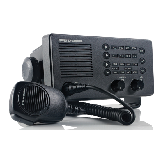
2. OPERATIONAL OVERVIEW 2.1 Controls BOTH IC 1 IC 2 IC 3 IC 4 YELP UNWY SAIL FUNC/PTT AUTOMATIC FUNC STOP ANCH AGND LISTEN HAIL PWR OFF LH-3000, front view Control description Chooses loud hailer speaker to use (ALL, FWD, AFT, [Hail Select] Key BOTH). -
Page 18: Turning The Power On/Off
2. OPERATION Activates automatic and manual warning signals. [FUNC] Key Adjusts listening volume from the internal speaker; turns [LISTEN VOL] Control power on/off. Adjusts output volume from the horn speakers or intercom [HAIL VOL] Control station speakers. From top row: LED Indicators - Hail indicators (ALL, FWD, AFT BOTH) - Intercom indicators (IC1 –... -
Page 19: Adjusting Key Backlighting
2. OPERATION 2.3 Adjusting Key Backlighting You may adjust the intensity of the key backlighting cyclically with the [DIM] key, in five levels, including off. 2.4 Adjusting Output Level Turn the [HAIL VOL] control to adjust the output volume from the horn speakers or intercom speakers. -
Page 20: Calling A Specific Intercom Station
2. OPERATION 2.7 Calling a Specific Intercom Station 1. Press the [Intercom Select] key until the indicator lights on the desired intercom station. After a one-second delay, a short tone sounds from the selected intercom station. 2. Press the PTT switch on the microphone and speak into the microphone. 3. -
Page 21: Hailing By Voice
2. OPERATION Manually selecting a calling station 1. Press the [Intercom Select] key until the indicator lights for the desired station. 2. Press the PTT switch on the microphone and answer the call. 3. Release the PTT switch to listen to the intercom station. Adjust listening volume with the [LISTEN VOL] control if necessary. -
Page 22: Sounding Warning Signals
2. OPERATION 2.10 Sounding Warning Signals Your Loud Hailer has eight different warning signals: two manual and six automatic. The two manual signals, YELP and MAN, are designed to be sounded at each press of the PTT switch on the microphone. The six automatic signals are sounded when the [FUNC] key is operated. - Page 23 2. OPERATION SAIL: Warning signal for sailboats, tug boats and tow boats underway. One 3-second blast, followed by one 2-second interval, one 1-second blast, one 2-second interval and one 1-second blast. Repeated every 120 seconds. 120 s Sailing signal TOW: Warning signal for vessels under tow.
- Page 24 2. OPERATION ANCH: Warning signal for vessels at anchor. A rapidly ringing bell tone sounds for a duration of 5 seconds, repeated at an interval of 60 seconds. 60 s Anchor signal AGND: Warning signal for vessels aground. Two bell tones of 0.5 seconds, a bell tone of 1 second followed by a rapidly ringing bell tone for a duration of 5 seconds, followed by a bell tone of 2 seconds and 0.5 seconds.
- Page 25 2. OPERATION Sounding an automatic warning signal 1. Press the [Hail Select] key until the indicator lights for the desired horn speaker(s). If no selection is made, “BOTH” will be automatically selected when a warning signal is initiated. 2. Press the [Upper Signal Select key] to select UNWY, SAIL or TOW or press the [Lower Signal Select] key to select STOP, ANCH or AGND until the indicator flashes for the desired signal.
-
Page 26: Transmitting The Auxiliary Signal
2. OPERATION 2.11 Transmitting the Auxiliary Signal Transmitting the auxiliary signal over all speakers An audio signal from an external audio source can be transmitted through the equipment via the AUX input connector on the rear panel. 1. In the standby mode, press the [AUX] key. The signal from the external AF source (radio, CD player, etc.) sounds from all intercom stations and any connected horn speakers. - Page 27 2. OPERATION Disabling the alarm mode Press any key or switch other than the [AUX] or [DIM] key, or turn off the power. Enable alarm ALL, FWD, AFT and BOTH indicators light. YELP indicator goes off. Press the [Lower Signal After 5 minutes Select] key to flash the YELP indicator.
-
Page 28: Siren Mode (Lh-3000-Cg)
2. OPERATION 2.13 Siren Mode (for LH-3000-CG) Enabling the siren mode The siren mode, activated by a switch connected to the burglar alarm terminal, functions to sound the warning signal (YELP) from both horn speakers in the standby mode. To interrupt the warning signal to speak, press the PTT switch on the microphone and speak into it. -
Page 29: Maintenance, Troubleshooting
3. MAINTENANCE, TROUBLESHOOTING Periodic checks and maintenance are important for maintaining performance. This chapter contains maintenance and troubleshooting instructions to be followed to obtain optimum performance and the longest possible life of the equipment. WARNING Do not open the equipment. Only qualified personnel should work inside the equipment. -
Page 30: Replacing The Fuse
3. MAINTENANCE, TROUBLESHOOTING 3.2 Replacing the Fuse The 6A fuse inside the Loud Hailer protects it from reverse polarity and equipment fault. If the power cannot be turned on, the fuse may have blown. Have a qualified technician check the fuse. WARNING Use the proper fuse. -
Page 31: Specifications
FURUNO LH-3000 SPECIFICATIONS OF LOUD HAILER LH-3000 AUDIO OUTPUT Hail speaker 20 W, 8 ohms Intercom speaker 4.0 W, 4 ohms External speaker 4.0 W, 4 ohms Internal speaker 2.2 W, 4 ohms INPUT IMPEDANCE MIC impedance 600 ohms Aux impedance... - Page 32 This page is intentionally left blank .
- Page 40 When a claim is made, FURUNO has a right to choose whether with other electronic devices. The imported product may also be to repair the product or replace it.
- Page 41 24 months from installation date provided the work is done by Furuno U.S.A., Inc. or an AUTHORIZED Furuno dealer during normal shop hours and within a radius of 50 miles of the shop location.
- Page 42 (title and/or number and date of issue of the standard(s) or other normative document(s)) For assessment, see • EMC Test Report FLI 12-04-005, February 20, 2004 prepared by Furuno Labotech International Co., Ltd. This declaration is issued according to the Directive 2014/30/EU of the European Parliament and of the Council of 26 February 2014 on the harmonisation of the laws of the Member States relating to electromagnetic compatibility.
- Page 44 The paper used in this manual is elemental chlorine free. ・FURUNO Authorized Distributor/Dealer 9-52 Ashihara-cho, Nishinomiya, 662-8580, JAPAN A : FEB 2004 Printed in Japan All rights reserved. E3 : APR . 26, 2017 Pub. No. OME-56460-E3 ( ETMI ) LH-3000...
Need help?
Do you have a question about the LH-3000CG and is the answer not in the manual?
Questions and answers