Table of Contents
Advertisement
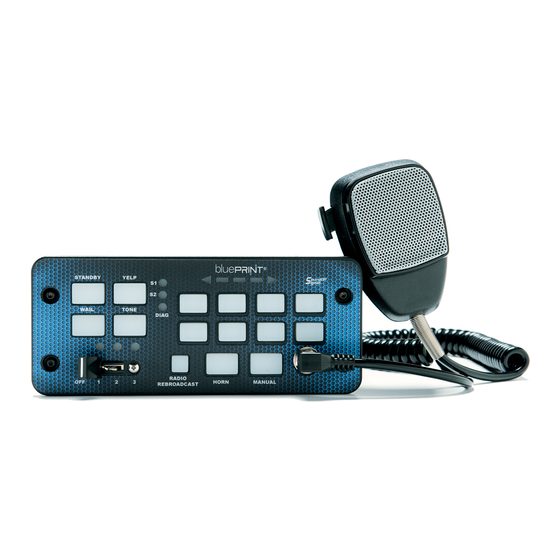
500 Series Control System & Siren Amplifier
Console Mount, Remote Mount, & Handheld
Part Numbers: ENGSA5(xxxSx)
WARNING
• HIGH CURRENT interconnects must be properly terminated. Poor crimp quality can cause heat build-up and fire. Follow crimp connector
manufacturer instructions. Always verify that the mating terminals for high current connectors use the same plating finish.
• DO NOT install this product or route any wires in the Air Bag Deployment Zone. Refer to vehicle Owner's Manual for deployment zones.
• DO NOT use system to disconnect headlights, brake lights or other safety equipment.
• Unit may become hot to touch during normal operation.
• Failure to properly install connectors, fuses or wiring may cause equipment or vehicle failure or fire.
• Installation must only be performed by trained technician. Installer must determine vehicle wiring configuration and proper integration of
system.
• Use proper wire gauge. All power wires connecting to positive (+) or negative (-) battery terminal or local chassis ground (-) must be sized
to supply at least 125% of max. current and properly fused at power source.
• Install protective grommets when routing wire through firewall or metal.
Installers and users must comply with all applicable federal, state and local laws regarding use and installation of warning devices.
Improper use or installation may void warranty coverage. To review our Limited Warranty Statement & Return Policy for this or any SoundOff Signal product,
visit our website at https://soundoffsignal.com/support-page/warranty/. All returned items must be properly packed to prevent damage in transit.
If you have questions regarding this product, contact Technical Services, Monday - Friday, 8 a.m. to 5 p.m. at 1.800.338.7337 (press #4 to skip the
automated message). Questions or comments that do not require immediate attention may be emailed to techgroup@soundoffsignal.com.
NOTICE:
For Technical Support - Please Call 1-800-338-7337
or visit
www.soundoffsignal.com
T
C
ABLE OF
ONTENTS
Rev. D - 07/2021
500 Series Control System and Siren Amplifier
2
2
2
2
3
3
4
4
5
5
6
6
7
8
9
11
11
12
12
13
14
Page 1
ENGSA5(xxxSx)
Advertisement
Table of Contents

Subscribe to Our Youtube Channel
Related Manuals for Soundoff Signal Blueprint 500 Series

Summary of Contents for Soundoff Signal Blueprint 500 Series
-
Page 1: Table Of Contents
Installers and users must comply with all applicable federal, state and local laws regarding use and installation of warning devices. Improper use or installation may void warranty coverage. To review our Limited Warranty Statement & Return Policy for this or any SoundOff Signal product, visit our website at https://soundoffsignal.com/support-page/warranty/. -
Page 2: Introduction
TOTAL 325 Amps SoundOff Signal is excited to be your partner for safety and we offer industry-leading service and support of this and all our products. *bluePRINT Link allows the programmer to choose from more than 50 vehicle signals for After fully reviewing these instructions, please contact us should you each of the 24 system inputs. -
Page 3: Hardware Installation & Wire Routing
& W ARDWARE NSTALLATION OUTING Amplifier Installation (Remote Mount) Locate a suitable mounting location. We recommend a cool, dry area. Before drilling holes, check for clearance to prevent damage to the amplifier or any other components being installed. Check both sides of the mounting surface before drilling and be aware of any vehicle components or other vital parts that may be damaged during drilling. -
Page 4: System Outputs
(B.O.B). This allows for direct connection (with no B.O.B.) using the nFORCE® Exterior Lightbar, or any of SoundOff Signal’s three-wire NOTE #1: The total current for these three outputs should not exceed type lightbars using an RJ-45 to single wire adapter (shown on page 50A. -
Page 5: Control Panel Bus #1 (Remote) & Optional Equipment
This port also supports connecting multiple external B.O.B.’s using CN11 – RJ-45 – Control Panel Databus Connectivity parallel CAT-5 splitters. This feature can be programmed through See the data bus connectivity schematic on page 12. SoundOff Central bluePRINT software. When using more than one external B.O.B., parallel splitters may be #2 (C ) / S ONTROL... -
Page 6: Programming
feature needs to be activated in the SoundOff Central bluePRINT Microphone to the control panel isn’t desirable. As an optional Software. It is not on by default. installation, the PA Microphone can be connected directly to the siren amplifier, using accessory kit PSRN5HDK3. Vehicle OEM’s typically use pulse width modulation frequencies from 100 to 250 Hz. -
Page 7: Diagnostic Functions And Notifications
Diagnostic Status LED Lights (Rear of Amplifier) IAGNOSTIC UNCTIONS AND OTIFICATIONS There are two different LED lights on the rear of the amplifier. Each Resetting Outputs LED light represents a different portion of the siren function. Should any of the solid state The upper light is marked “OUTPUT STATUS.”... -
Page 8: Tech Specs & Replacement Parts
& R PECS EPLACEMENT ARTS ECHNICAL PECIFICATIONS ARNESS SSEMBLY UMBERS UILD YOUR OWN General Information Part Description Amplifier Dimensions 2.63" H x 7" W x 7" D Crimp Ferrule Connection (over bare wire) Connector Ferrule Crimp Tool: American Electrical SQ28-10 (or equivalent) Full Size Control Panel 3.6"... -
Page 9: Schematics
Main Power Input - Pass through to internal power lug* 75A Max Green / Black Relay 1 - Normally Open * Connec�on is on the inside of the amplifier. See page 3 for more detail Green / White Relay 1 - Normally Closed Green Relay 1 - External Input*** Blue... - Page 10 Siren Amplifier Fuse 100w = 15A Future Expansion 200w = 25A Orange Speaker A Out Orange Future Expansion Orange / Black Speaker A Out Light Blue / Red CAN A + Green Speaker B Out Blue Radio Rebroadcast / External PA Input 1 Green / Black Speaker B Out Light Blue / Black...
-
Page 11: Horn Ring Examples
LIN B XAMPLES XAMPLES Low Current Horn Ring - 5A Max - Positive or Negative LIN Bus connections include Remote Nodes and Input Nodes. These can be connected using the same wire, connected in parallel, or by using junction points as shown below. Input Nodes are only necessary when using additional discrete inputs beyond the eight provided inputs from the 500 Series Control System. -
Page 12: Lightbar Data Port Bus Examples
IGHTBAR XAMPLES RJ-45 UILDING AN TO THREE WIRE CONTROL ADAPTER Internal Lightbar Control Example Using a standard RJ-45 Connector Optional RJ-45 to Three Wire Control Adapter* and a short length of CAT-5 cable, insert the blue pair of wires into pins #4 and #5 and then crimp Lightbar Data Bus 1 Lightbar Data Bus 1... -
Page 13: Control Panel Bus #2 Example
#2 (C #2 E ONTROL ANEL ONSOLE XAMPLES ONTROL ANEL XAMPLE Console or Remote Control Panel with PA Connection at Control Panel (Inside View) ONTROL ANEL PA Mic Remote Control Panel with PA Connection at the Siren (Inside View) ONTROL ANEL *Any remote bluePRINT Control Panel can be installed, including... -
Page 14: Relay Outputs With Inductive Loads
ELAY UTPUTS WITH NDUCTIVE OADS ELAY UTPUTS WITH NDUCTIVE OADS NDUCTIVE OADS Inductive loads are a type of electrical load found in devices that convert electrical current into a magnetic field. In electronics, this covers just about any device that utilizes a coil. Switched 12vdc Switched Ground One of the characteristics of inductive loads is how...
Need help?
Do you have a question about the Blueprint 500 Series and is the answer not in the manual?
Questions and answers