
Related Manuals for OSS OSS-PCIE-4UV-5-1


Summary of Contents for OSS OSS-PCIE-4UV-5-1
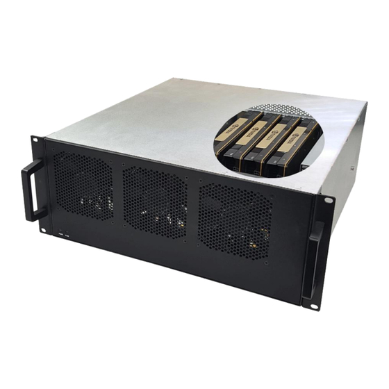
- Page 1 4U Value Gen4 5-Slot 5 PCIe (4.0 x16) Slot Expansion System 4U Value 5-Slot Chassis Gen4 User Manual SKU: OSS-PCIE-4UV-5-1 www.onestopsystems.com...
-
Page 2: Table Of Contents
Configuration: TWO cables ..............................24 2.6.3 x4 Configuration: ONE cable ................................. 25 2.6.4 Disconnecting the cable ................................26 Applying Power Correctly ..............................27 Connect Power Cord ..................................27 Connecting to electrical outlet................................28 Power ON the Host Computer ................................28 OSS-PCIe4-4UV-5... - Page 3 Slot LED Status indicators ................................58 Check PCIe cards on Windows OS (i.e. Server) ..........................59 Check PCIe cards on Linux OS ................................59 Check PCIe cards on Mac OS ................................59 General & Other Technical Information .........................60 10.1 Board LEDs ....................................60 OSS-PCIe4-4UV-5...
- Page 4 Frequently Asked Questions (FAQ) ..........................85 Contacting Technical Support ............................87 Third Party Hardware and Software Support Policy .......................87 Returning Merchandise to One Stop Systems ........................88 Shipping / transporting the unit ............................88 APPENDIX A Compliance .............................89 FCC ..........................................89 CE ..........................................89 OSS-PCIe4-4UV-5...
- Page 5 One Stop Systems OSS-PCIe4-4UV-5...
-
Page 6: Preface
Disclaimer: We have attempted to identify most situations that may pose a danger, warning, or caution condition in this manual. However, One Stop Systems does not claim to have covered all situations that might require the use of a Caution, Warning, or Danger indicator. OSS-PCIe4-4UV-5... -
Page 7: Safety Instructions
Also, before connecting a cable, make sure both connectors are correctly oriented and aligned. CAUTION Do not attempt to service the system yourself except as explained in this manual. Follow installation instructions closely. OSS-PCIe4-4UV-5... -
Page 8: Protecting Against Electrostatic Discharge
Handle all sensitive components at an ESD workstation. If possible, use anti-static floor pads and workbench pads. Handle components and boards with care. Do not touch the components or contacts on a board. Hold a board by its edges or by its metal mounting bracket. OSS-PCIe4-4UV-5... -
Page 9: Introduction
PCIe Switch 88032 Half Height, half length, single slot x16 PCIe add-in card form factor PCIe4 x16 physical card edge connector (256Gb/s) Backplane: Two OSS-PCIe4-BP-5X16 (522 board) - PCIe switch 88096 - PCIe 3 5-slot expansion backplane The 5-slot integrated system includes:... -
Page 10: Features
One PCIe 4.0 x16 host connections Four x16 mini-SAS HD PCIe cables PWM fan options Two 2000W load-sharing power supplies AUX power connectors for high power AICs 1.3 Block Diagram 1.3.1 Enclosure 1.3.2 Backplane OSS-PCIe4-4UV-5... -
Page 11: Host And Backplane
By default, the expansion unit is shipped out from the manufacturer with the expansion backplane mounted closest to the power supply. The expansion unit is attached to one host server / computer. A single Host Cable adapter card is installed in the host computer. One Target card in the expansion backplane.. OSS-PCIe4-4UV-5... -
Page 12: Model 2
One Stop Systems 1.4.2 Model 2 The location of the expansion backplane is mounted on the far right-end side in the enclosure. OSS-PCIe4-4UV-5... -
Page 13: Pcie Card / Gpu Configuration
The 4UV Gen4 5-slot expansion backplane will support up to five full-length single-wide GPUs or four full-length double-wide GPUs. The GPUs are installed on the PCIe x16 Gen4 PCIe slot. Single-wide GPU configuration: You can fit 5 single-wide GPUs on the expansion backplane Double-wide GPU Configuration: The Gen4 expansion backplane can only accommodate four double-wide GPUs. OSS-PCIe4-4UV-5... - Page 14 One Stop Systems Combo GPU Configuration: You can install a combination of double-wide GPUs and single-wide GPUs. Combo GPU Config1 Combo GPU Config2 It is strictly recommended to install the same brand / maker of GPUs. OSS-PCIe4-4UV-5...
-
Page 15: Main Components
The 4U Value GPU Accelerator Systemic composed of following major components Single5-slot Backplanes One Target Card : PCIe 4.0 x16 One Host Card: PCIe 4.0 x16 Four SFF-8644 PCIe Gen4 PCIe Cables One or Two 2000W Power Supplies Three 120mm x 38mm Fans (250cfm) 1.7 Parts Overview OSS-PCIe4-4UV-5... - Page 16 One Stop Systems OSS-PCIe4-4UV-5...
-
Page 17: Pre-Installation Information
To complete the installation of the product you will need a Phillips-head screwdriver and ESD wrist strap to prevent electrostatic discharge. 1.10 Items List Item Description Full-height PCI Express Adapter Cards SFF – 8644 x16 PCIe Gen4 cable U.S. Standard 125V or 250V 1 set Rackslide and Kit (Optional) OSS-PCIe4-4UV-5... -
Page 18: Hardware Set-Up / Installation
This will help you in troubleshooting the problem more easily and efficiently. If everything works well and no configuration issues, you can proceed with the installation of the remaining 3 party PCIe cards. Always refer to or read “3 party manufacturer installation guide” for further instructions. OSS-PCIe4-4UV-5... -
Page 19: Before You Begin
Remove the five (5)mounting screws on top of the chassis. Slide the enclosure cover towards the front of the unit to disengage it from the guides until it clears the back hold-down, and then lift the cover off. Check inside the unit; make sure the “Target Adapter Card “is fully seated in the Upstream slot. OSS-PCIe4-4UV-5... -
Page 20: Install Target Card
One Stop Systems 2.4 Install Target Card By default the “Target card (OSS-PCIe-HIB616-x16)”is installed in the target slot / upstream slot of the expansion system. Check the switches on the Target card, make sure it is configured to Target mode.See photo below for the Target mode switch settings. -
Page 21: Target Card Configuration
SW2 #1 = OFF; #2 = ON or #2 = OFF and #1 = ON x4 Dip switch Settings SW1 #2 = ON; #5 = ON SW2 = All OFF 2.5.2 Target Card Configuration SW1 #1 = ON; #2= ON SW2 = All OFF OSS-PCIe4-4UV-5... - Page 22 Express cards without brackets may fit into conventional PCI slots, you run the risk of damaging the PCI Express host card if you insert it into a PCI slot. Please ensure that your host computer has PCI Express slots and install the host card only into a PCI Express slot. OSS-PCIe4-4UV-5...
-
Page 23: Connect Link Cables
Plug-in the 3 cable to Port#2 on both Target and Host cards Plug-in the 4 cable to Port#3 (Bottom port) on both Target and Host cards Note: It is easier to plug in the cables starting from bottom to top. OSS-PCIe4-4UV-5... -
Page 24: X8 Configuration: Two Cables
On the host card, you can move the two PCIe cables to the bottom ports. 1 Cable to PORT #2 and the 2 cable to PORT #3 Note: The two cables on the TARGET card should not be removed from PORT #0 and PORT #1. See diagrams below as an example. OSS-PCIe4-4UV-5... -
Page 25: X4 Configuration: One Cable
Photo B1: Cable on the Target card is connected to PORT #0. The other end of the cable is connected to PORT #2 on the Host card. Photo C1: Cable on the Target card is connected PORT #0. The other end of the cable is connected to PORT #3 on the Host card. OSS-PCIe4-4UV-5... -
Page 26: Disconnecting The Cable
One Stop Systems Diagrams below are different x4 cable configurations. 2.6.4 Disconnecting the cable To disconnect the link cable, pull back the PLASTIC thumb tab to release metal pins while slowly pulling the cable out. OSS-PCIe4-4UV-5... -
Page 27: Applying Power Correctly
Power Cord PSU Watt Voltage AMPS 125V 1000W 100-127V 12-9.5A 50-60Hz 250V 1800W 200-220V 10-9.5A 50-60Hz 250V 1980W 220-230v 10-9.8A 50-60Hz 250V 2000W 230-240V 10-9.8A 50-60Hz NOTE: When using 115-125V power cord you are limited to 1000W of power. OSS-PCIe4-4UV-5... -
Page 28: Connecting To Electrical Outlet
If you are using a 250V power cord, you would need to connect that to a PDU (power distribution unit). You can buy the PDU on any online electronic stores. OSS does not sell the PDU. 3.3 Power ON the Host Computer Before powering ON the Host computer, make sure the Host adapter cards are seated correctly in the PCIe slot and the cables are firmly connected. -
Page 29: Power On The Expansion Unit
ON or OFF. The expansion unit will turn ON automatically upon powering up the Host computer. The two front LEDs (PWR and FAN) will come ON as “solid-green”. The green LED indicates that the chassis is powered. Powering down the Host computer turns OFF the expansion system. OSS-PCIe4-4UV-5... -
Page 30: Hardware Check
Blinking Green: The CARD EDGE connector is communicating to Gen3 PCIe switch on the expansion board / backplane. Solid Green: Gen 4 on the expansion chassis switch ON (Blinking Green) Power Good / FPGA Healthy ON (Solid Green) AUX Power Good OSS-PCIe4-4UV-5... -
Page 31: X8 Configuration Leds (Two Cables)
Blinking Green: The CARD EDGE connector is communicating to Gen3 PCIe switch on the expansion board / backplane. Solid Green: Gen 4 on the expansion chassis switch ON (Blinking Green) Power Good / FPGA Healthy ON (Solid Green) AUX Power Good OSS-PCIe4-4UV-5... - Page 32 Solid Green: Gen 4 on the expansion chassis switch Blinking Green: The CARD EDGE connector is communicating to Gen3 PCIe switch on the expansion board / backplane. ON (Blinking Green) Power Good / FPGA Healthy ON (Solid Green) AUX Power Good OSS-PCIe4-4UV-5...
-
Page 33: X4 Configuration Leds (One Cable)
The Photo below is the link LED on the Host card, set to x4 and with single cable connected to top PORT #0. Photo below is the link LED on the Host card, set to x4 and with single cable connected to PORT #1. OSS-PCIe4-4UV-5... - Page 34 The CARD EDGE connector is communicating to Gen4 PCIe switch on the host computer motherboard. Blinking Green: The CARD EDGE connector is communicating to Gen3 PCIe switch on the expansion board / backplane. ON (Blinking Green) Power Good / FPGA Healthy ON (Solid Green) AUX Power Good OSS-PCIe4-4UV-5...
-
Page 35: Re-Install Top Cover
Both LEDs on the Power Supply should be ON as solid green, it indicates the OK status of the DC GOOD signal. The LED shall continue to glow under normal operation of the power supply. If this LED is blinking or not lit or in amber color, the power supply is not operating properly. OSS-PCIe4-4UV-5... -
Page 36: Software Installation
Mac OS, which means no installation of One Stop Systems driver. Before attempting to install anything on a Windows system, you should ensure that you have set a Restore Point, that all data files are closed and that you have a current backup of your data. OSS-PCIe4-4UV-5... -
Page 37: Verify Hib Device
The output below gives you B/D/F numbers, the device Class, the Vendor name and Sub Vendor name. To check on the revision of the card, use the command below. #lspci –vmms ac:00.0 See output below. To check on the PCIe Gen speed and Link Width #lspci –nvvs b8:00.00 | grep ‘LnkCap\|LnkSta’ OSS-PCIe4-4UV-5... - Page 38 One Stop Systems To display more details or information lspci –nvvs ac:00.00 OSS-PCIe4-4UV-5...
- Page 39 The output below shows only the Host is being detected. The Host card is not connected to the Target card. To check or to identify whether the bus XX:XX.0 is the Upstream port and Downstream port, on the terminal window type lspci –s ac:00.0 - vvv | grep ‘Capabilities\|Port\|LnkSta\|LnkCap’ or lspci –nvvs –ac:00.00 | grep ‘Capabilities\|Port\|LnkSta\|LnkCap’ OSS-PCIe4-4UV-5...
- Page 40 Check Host Adapter card The OSS Gen4 PCIe switch will show up in lspci even if it is installed alone and no cables are connected to the card. You can check or verify if the OSS Gen4 Host adapter card is detected or not by using the following commands.
-
Page 41: Windows 10 / Server
The photo below is showing multiple layers of PCI Express standard Upstream Switch Port and PCI Express standard Downstream Switch Port. Displaying a link between Host and Target cards. Photo below is only showing a single Host device is detected. OSS-PCIe4-4UV-5... - Page 42 Displaying a link between Host and Target cards. Showing a PCIe device (i.e. NVIDIA card) is recognized. The PCIe device is the 3 party PCIe card installed into the downstream slot of an expansion backplane. The screenshot below depicts that only the Host card is detected. OSS-PCIe4-4UV-5...
-
Page 43: Verify Expansion Backplane
On Linux operating system, to verify or check if the board is detected or not, type the following commands on the terminal window. $lspci –vvv | grep c012, see output below: $lspci –tvvv | grep LSI, see output below $lspci –m | grep 00b2, see output below. OSS-PCIe4-4UV-5... - Page 44 One Stop Systems $lspci –vvvt, this will give you the entire devices in a tree format. Output below is a cropped screenshot of the lspci –tvvv showing the OSS-522 backplane with no PCIe cards installed. OSS-PCIe4-4UV-5...
-
Page 45: Check And Verify Pcie Cards
Output below is a cropped screenshot of the “lspci –tvvv” showing the OSS-522 backplane with five cards installed. Output below is a cropped screenshot of the “lspci –tvvv” showing the OSS-522 backplane with a single card installed in SLOT# 5 Output below is a cropped screenshot of the “lspci –tvvv”... - Page 46 One Stop Systems Output below is a cropped screenshot of the “lspci –tvvv” showing the OSS-522 backplane with a single card installed in SLOT# 2. Output below is a cropped screenshot of the “lspci –tvvv” showing the OSS-522 backplane with a single card installed in SLOT# 3.
-
Page 47: Windows
The screenshot below shows five PCIe cards that are detected but showing a yellow exclamation mark next to it, which means the driver is not loaded. You can obtain the driver from the card manufacturer or you can download it from the vendor’s website. OSS does not provide 3 party driver / software. - Page 48 One Stop Systems The screenshot below shows NO PCIe cards are installed on the OSS-522 backplane. OSS-PCIe4-4UV-5...
-
Page 49: Check Pcie Cards On Windows
One Stop Systems The screenshot below shows the 5 PCIe slots on OSS-522 backplane (Gen4 PCIe expansion board). 7.2.1 Check PCIe cards on Windows Below screenshot is showing the OSS-522 backplane with a single PCIe card installed in SLOT# 1 OSS-PCIe4-4UV-5... - Page 50 One Stop Systems Below screenshot is showing the OSS-522 backplane with a single PCIe card installed in SLOT# 2 Below screenshot is showing the OSS-522 backplane with a single PCIe card installed in SLOT# 3 OSS-PCIe4-4UV-5...
- Page 51 One Stop Systems Below screenshot is showing the OSS-522 backplane with a single PCIe card installed in SLOT# 4 Below screenshot is showing the OSS-522 backplane with a single PCIe card installed in SLOT# 5 OSS-PCIe4-4UV-5...
-
Page 52: Pcie Card Installation
8.2 Open PCIe Expansion Chassis Unscrew the four screws on the front of the unit and slide the lid towards the front as shown below: Remove slot covers OSS-PCIe4-4UV-5... -
Page 53: Installation Of Gpu
Be very careful and cautious when plugging in a GPU into a PCIe slot. Failure to align the GPU on the slot can damage one of the components. See picture below as an example of a detached / damaged components. OSS-PCIe4-4UV-5... -
Page 54: Install Gpu Cards
Install GPU card one at a time starting from RIGHT to LEFT (see reference photos below). Align the card on top of the slot. Gently push the card down until it is firmly seated. Make sure that all GPU cards are secured. OSS-PCIe4-4UV-5... - Page 55 One Stop Systems Make sure all the GPUs are firmly secured before connecting the aux power cables! OSS-PCIe4-4UV-5...
-
Page 56: Connect Aux Power Cable
Velcro to hold or tie down the cables. For acceptable cable management versus poor cable management, see photos below. NOTE: Do not operate or run the unit with the cables blocking the fan as this can impede the airflow and can lead the GPU cards to overheat. OSS-PCIe4-4UV-5... -
Page 57: Re-Install Top Cover
The system should be up and running, the next step is to check and verify whether the PCIe cards are detected or not. Use the procedures detailed in Chapter 6 to confirm the card installation(s) in the Windows Device Manager, Linux and Mac OS. OSS-PCIe4-4UV-5... -
Page 58: Pcie Hw Verification
Blink 2Hz = Gen3 Link Blink 1Hz = Gen2 Link Blink 0.5Hz = Gen1 Link (Slow Blinking) OFF = No card installed Check the LINK LEDs on both Host and Target cards, go to Chapter 4 for more information. OSS-PCIe4-4UV-5... -
Page 59: Check Pcie Cards On Windows Os (I.e. Server)
9.3 Check PCIe cards on Linux OS To check on PCIe cards or GPU cards on Linux OS, type lspci – vtt or lspci–tv command on the terminal window. Go to section 6.1.1 for more details 9.4 Check PCIe cards on Mac OS Not tested. OSS-PCIe4-4UV-5... -
Page 60: General & Other Technical Information
Aux Power LED Auxiliary Board power LED This is GREEN, denotes existence of auxiliary Board is at fault / error power +5VAUX LED Name Target LED SLOT 1 SLOT 2 SLOT 3 Reset Slot 4 Slot 5 LED Component PCIe Connector OSS-PCIe4-4UV-5... -
Page 61: Pcie Slot Type
10.3 Force Power ON The board has a connector for a shunt / jumper, which allows the backplane to force the ATX supply to power ON. See photos below for the location of the J1 connector on the backplane. OSS-PCIe4-4UV-5... -
Page 62: Power Cords
One Stop Systems 10.4 Power Cords Two types of power cords can be used with this expansion unit, 125V and 250V. 10.4.1 Specifications OSS PART#: 290-001-012-RC (125V) OSS PART#: 290-001-032-RC (250V) Description: CORD NEMA5-15P C-13SJT Description: CORD PWR MALE-FEMALE SJT... -
Page 63: Power Supply
(MTBF) of greater than 200,000 hours and an LED indicator to keep you informed on normal/abnormal conditions for your PSU. This power supply is redundant to safe-guard your system from power failure and allows for hot-swap replacement to eliminate system downtime. All materials contained comply with RoHS requirements. OSS-PCIe4-4UV-5... -
Page 64: Specifications
+5V: N/A +3.3V : N/A Environmental Specifications Temperature 0 to 50 degree C Operating Altitude 16,5000 feet Operating Relative Humidity 20% to 90% RH Operating Safety Regulations UL, cUL, BMSI, CQC, CB, CE, FCC Class A, CISPR Class A, ROHS OSS-PCIe4-4UV-5... -
Page 65: Led Indicator
When the unit is in standby with no AC is present, the LED should be off. When the unit is turned on properly, the LED is green. During wakeup redundancy mode, the LED should be Green. OSS-PCIe4-4UV-5... -
Page 66: Fan
Max. Static Pressure 1.48” H²O Weight ~375 g Weight ~375 g Tachometer – Open Collector | PWM Tachometer – Open Collector *Connection *Connection UL1007, 24AWG, ~320mm UL1007, 24AWG, ~320mm Red (+) Black(-) White: Tachometer Blue: PWM Red (+) Black(-) White Tachometer OSS-PCIe4-4UV-5... -
Page 67: Auxiliary Power Cables
290-010-037-RC- Cable Assy, Aux Pwr, 8 Pin, NVIDIA 2.0, 12", Expansion System, 8-pin male to 8-pin male One 8-pin connector M176 (OSS) 290-010-037-RC- Cable Assy, Aux Pwr, 8 Pin, NVIDIA 2.0, 24" Expansion System, 8-pin male to 8-pin male One 8-pin connector... -
Page 68: Aux Power Cable Installation
There are eight available 8 ports / connections on the power supply backplane in which you can plug in the aux power cables. You can only use the OSS supplied 8-pin and 6+2 pin aux power cables ( 290-010-037-RC-01/02, 290-010-013-RC and 290-010-036-RC). -
Page 69: Pin Outs
One Stop Systems 10.7.2 Pin Outs PSU board aux port pin outs 8-pin aux power cable and pin outs OSS-PCIe4-4UV-5... - Page 70 One Stop Systems 6+2-pin aux power cable and pin outs OSS-PCIe4-4UV-5...
-
Page 71: Using The Auxiliary Power Cable
The photo below is an example of a PCIe card or GPU card that has two 6-pin power connectors. You need two 6+2-pin aux cables to provide extra power. The photos below are example of a PCIe card or GPU card that has a 6pin power connector. You need one 6+2pin aux cable to provide extra power. OSS-PCIe4-4UV-5... - Page 72 8-pin aux cable to provide extra power. Each PCIe x16 slot on the 522 OSS board provides 75 Watts of power which is adequate for most video cards. But a high-end GPU cards usually need more power. To accommodate graphics cards needing more than 75 watts, the PCI-SIG (Special Interest Group) introduced two standards for supplying additional power to a video card via additional graphics power connectors: ...
-
Page 73: Expansion System Power Consumption
15 Watt per card Fans 44.4 Watt per fan Backplane Typical is 40 Watt min, Worst Case is 50 Watt max (per backplane) Three Fans: 132 Watts Two Target cards: 30 Watt Two boards: 100 Watts (max) OSS-PCIe4-4UV-5... -
Page 74: Fan Controller
There are three fans located at the front of the enclosure to provide cooling required for the hottest PCI Express cards. As safety measure, by default the OSS provides 4U 10-slot Value expansion chassis with the... -
Page 75: Specifications
Approx 110 g Insulation resistance 10 MΩ or higher using a 500 VDC insulation resistance tester. Between the power supply input terminal and case Dielectric strength 500 VAC (50/60 Hz) for 1 minute Between power supply input terminal and case OSS-PCIe4-4UV-5... -
Page 76: Troubleshooting
Repeat this until all cards have been tested. If they all test OK, then add the card one at a time until you find the combination that does not work. If you find that one of your card is bad card, replace it, you fixed it! OSS-PCIe4-4UV-5... -
Page 77: My Pcie Card Doesn't Work
Windows or Mac computer as if the expansion chassis WAS the desktop computer. When correctly installed, there is no difference to the operating system, removable cards, or most software. OSS-PCIe4-4UV-5... - Page 78 BIOS firmware) should be provided by your computer vendor on their web site. In case this property is editable, you computer vendor should also be able to tell you how to select at least 32KB using their BIOS interface. OSS-PCIe4-4UV-5...
-
Page 79: System Board Fails To Power Up
12.6 System board fails to power UP A faulty 0SS board can cause the expansion system not to power UP properly. For troubleshooting, you can force power ON the OSS board by placing a jumper on J1 connector, see photos below. This will help you determine whether the board is functioning properly. You need the following items to perform this task. -
Page 80: Expansion System Fails To Turn On
Shutdown the system (computer and expansion unit). Disconnect the link cables. Remove the Target and Host cards. Check the target and host cards, make sure you have the correct model OSS-PCIe-HIB38-x16-F. Check the switch settings on the target card. Check the switch settings on the host card. -
Page 81: Rackslide Installation
One Stop Systems Rackslide Installation Remove Inner from the middle-outer rail Install inner rail to both sides of the chassis OSS-PCIe4-4UV-5... - Page 82 One Stop Systems Install mid-outer rail onto rack post Insert chassis into middle-outer rail on the rack OSS-PCIe4-4UV-5...
-
Page 83: Enclosure Dimensions
One Stop Systems Enclosure Dimensions OSS-PCIe4-4UV-5... -
Page 84: Rackslide Mounting Position
One Stop Systems Rackslide Mounting Position OSS-PCIe4-4UV-5... -
Page 85: Frequently Asked Questions (Faq)
14. Can I unplug the link cables while the expansion unit and the host computers are running? Answer: It is not recommended to unplug or plug in the link cables (x16 cable) while the expansion unit and host computers are running as this can cause failure. OSS-PCIe4-4UV-5... - Page 86 Answer: You can install a total of 8 double-wide / dual-width GPUs. Four dual-width / double-wide GPUs per 522 OSS board. 18. How many single-width / single-wide GPU can I install in the unit? Answer: You can install a total of 10 single-width / single-wide GPUs in the unit. Five single-width / single-wide GPUs per 522 OSS board.
-
Page 87: Contacting Technical Support
We test, certify and support many third party hardware and software products along with OSS hardware and are happy to integrate a fully supported system. Ask us about that service and we would be happy to help. If an OSS product is fully functional and a support issue is related to third-party hardware or software that did not ship from the OSS factory, the customer requesting support should reach out to the third- party vendor for assistance to fully troubleshoot the issue. -
Page 88: Returning Merchandise To One Stop Systems
Returning Merchandise to One Stop Systems If factory service is required, you must contact OSS Service Representative to obtain a Return Merchandise Authorization (RMA) number. Put this number and your return address on the shipping label when you return the item(s) for service. One Stop Systems will return any product that is not accompanied by an RMA number. -
Page 89: Appendix A Compliance
This Class A digital apparatus complies with Canadian ICES-003. Cet appareil numériqué de la classe A est conformé à la norme NMB-003 du Canada The product(s) described in this manual complies with all applicable European Union (CE) directives. One Stop Systems will not retest or recertify systems or components that have been reconfigured by customers OSS-PCIe4-4UV-5... - Page 90 One Stop Systems OSS-PCIe4-4UV-5...
Need help?
Do you have a question about the OSS-PCIE-4UV-5-1 and is the answer not in the manual?
Questions and answers