Table of Contents
Advertisement
Quick Links
Installation & Owner's
Manual
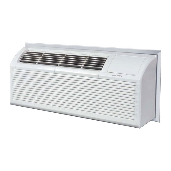
Packaged Terminal
Air Conditioner/Heat Pump
PTAC**5 & PTHP**5
Due to updates and constantly improving performance, the information and instructions
within this manual are subject to change without notice. Please visit
www.mrcool.com/documentation to ensure you have the latest version of this manual.
Version Date: 06-25-21
Advertisement
Table of Contents

Related Manuals for MrCool PTAC 5 Series


Summary of Contents for MrCool PTAC 5 Series
- Page 1 Air Conditioner/Heat Pump PTAC**5 & PTHP**5 Due to updates and constantly improving performance, the information and instructions within this manual are subject to change without notice. Please visit www.mrcool.com/documentation to ensure you have the latest version of this manual. Version Date: 06-25-21...
-
Page 2: Table Of Contents
Installation ......................Care & Cleaning ..................... Troubleshooting ....................DISCLAIMER: The images and illustrations used in this manual are for demonstration and explanation purposes only. The actual shape and size of the unit and components therein may vary. Page 1 mrcool.com... -
Page 3: Warnings
DO NOT use the socket if it is damaged or loose. It could cause fire and/or electric shock. DO NOT open the unit while it is operating. It could cause electric shock. DO NOT disassemble or modify the unit. It could cause electric shock. mrcool.com Page 2... - Page 4 It must be replaced with a cord from the product manufacturer. The illustration below represents different types of power cords (dependent on model). Power Cord Power 230V 230V 230V 265V 265V 265V Supply Page 3 mrcool.com...
-
Page 5: Cautions
DO NOT operate the unit without filters. This could cause unit failure. DO NOT operate the unit in a room where it could be exposed to excessive amounts of water such as a bathroom or laundry room. mrcool.com Page 4... -
Page 6: Operation Of Current Detection Device
If the power cord is damaged, it cannot be repaired. It must be replaced by one obtained from the product manufacturer. When 265V units are installed, the power supply must be a part of permanent wiring. Permanent wiring may be done through the accessory sub-base. An exposed cord connection on 265V units is not permitted. Page 5 mrcool.com... -
Page 7: Air Conditioner Features
This function turns on when the room temperature falls to 8°F (4.5°C) below set temperature of the unit. During this process, the reverse cycle heat is shut off and the electric heat strip is turned on for one cycle until heating is satisfied. mrcool.com Page 6... -
Page 8: Control Panel Operation
Please see the DIP Switch Configurations cycling with the compressor. section for further information. Page 7 mrcool.com... - Page 9 64°F-125°F (18°C-52°C) . NOTE: This air conditioner is designed to be operated in the temperature ranges listed in the table above. If the unit is operated outside of these temperature ranges, performance could be reduced. mrcool.com Page 8...
-
Page 10: Dip Switch Configuration (Optional)
Use control Panel or types of Use Control Panel Only To use Control Panel or some S9 (with wall thermostat, the other types of wall thermostat S3 Down) one must be turned off Sw11 Load Delay for 3 seconds Normal Optional Page 9 mrcool.com... - Page 11 This setting enables the fan to cycle on and off with the compressor or electric heater. The fan will stop a short time after the set temperature has been reached. Temperature Set-Point Limits Enables a restricted rang of temperature control. mrcool.com Page 10...
-
Page 12: Dip Switch Configuration By Panel Control (Optional)
3. After all the settings have been set, press the up (+) and down (-) buttons together for 3 seconds to exit the operation interface and turn off the power. Once power is turned back on, the settings will be activated. Page 11 mrcool.com... -
Page 13: Wall Thermostat Terminal (Optional)
Installation instructions of some types of wall thermostats (it may be necessary to consult with the retailer or manufacturer for details.) Pull the DIP switch to the Down (Off) position as shown in Fig. 5.2. Fig. 5.2 mrcool.com Page 12... - Page 14 If the wall thermostat has only one electrical heater output, connect the two terminals of HEAT 1 and HEAT 2. The unit can operate two electrical heaters (if the unit has two electrical heaters). DO NOT remove the control panel. Page 13 mrcool.com...
-
Page 15: Installation
Please refer to Fig. 6.3. CAUTION Use caution when picking up or moving the unit as there are sharp edges that can cause injury. Use two people when lifting the air conditioner as it is heavy. Fig. 6.3 mrcool.com Page 14... - Page 16 first placing the tabs of the panel over the top rail of the unit. Second, push inward at the bottom of the panel until it snaps into place. Please refer to Fig. 6.6. Fig. 6.6 Page 15 mrcool.com...
-
Page 17: Care & Cleaning
3. Run water through the filters. 4. Dry the filters thoroughly before replacing. 5. To replace the air filters, insert each filter back into their respective slots on the front panel and push down until it slides back into place. mrcool.com Page 16... - Page 18 5. Clean the filter and dry it thoroughly before reinstalling it. 6. Reinstall the vent door, filter, and four screws. 7. Then, reinstall the vent door steel wire into the hole of the vent door. Fig. 7.3 Page 17 mrcool.com...
-
Page 19: Troubleshooting
1. If the circuit breaker is tripped, or a fuse has blown, more than once, please contact a qualified electrician. 2. If the unit has been installed where condensation could drip in an undesirable location, an accessory drain kit should be installed and connected to the drain system. mrcool.com Page 18... - Page 20 Compressor Protection - To prevent short-cycling of the compressor, there is a random start-up delay of 3 minutes and a minimum compressor run time of 3 minutes. ELECTRIC HEATING FAILURE Clean the evaporator once every 3 months by a qualified technician or professional. Page 19 mrcool.com...
- Page 21 Packaged Terminal Air Conditioner/Heat Pump PTAC**5 & PTHP**5 The design and specifications of this product and/or manual are subject to change without prior notice. Consult with the sales agency or manufacturer for details.
Need help?
Do you have a question about the PTAC 5 Series and is the answer not in the manual?
Questions and answers