
Related Manuals for 4Ddoors 4DR1 v4

Summary of Contents for 4Ddoors 4DR1 v4
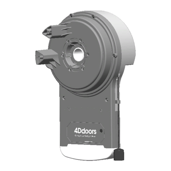
- Page 1 Installation instructions and Owner's manual Roller door operator 4DR1 v4 READ THIS MANUAL CAREFULLY BEFORE BEGINNING INSTALLATION Installer: Permanently attach manual to the wall. 4DOMU01A-2...
- Page 2 Inventory U-bolt + Saddle x1 set Anti-Coning Clip x2 sets Operator Unit Remote Handset x2 Wireless Wall Button x1 Weight Bar & mounting screw set x1 Manual + Safety Label Optional Accessories Items and quantity may differ to images shown...
- Page 3 PECIFICATION Electrical Rating Input AC 220V 50/60Hz Max. Current Power 100W Standby Power <2W Motor Type DC 24V Max. Capacity 1000N Recommended Lifting Forces Max. Lifting Force 60kg Rated Lifting Force 40kg Door Type Max. Door Size 20.5m Max. Door Height 4.6m Door Travel Limits 4.5 turns of door drum approx.
-
Page 4: Table Of Contents
ABLE OF ONTENTS Pre-Installation Notes Important Notices Installation Instructions Connectors Setting Direction of Operation Setting UP-Limit Setting DOWN-Limit Sensitivity Auto-Learning Manual Sensitivity Adjustment (For Installers Only) Programming Transmitter Setting Auto-Closing Timer Trouble-Shooting Parts Breakdown Parts List Warranty NSTALLATION OTES The operator may be fitted to either the RIGHT or LEFT hand side of the roller door. Check that there is sufficient side clearance to fit the operator unit as below listed: Door Type Minimum side clearance... -
Page 5: Important Notices
MPORTANT OTICES IMPORTANT : PLEASE READ THESE INSTRUCTIONS CAREFULLY PRIOR TO COMMENCING THE INSTALLATION OF THE OPERATOR UNIT. This Automatic Operator has been designed to provide years of trouble-free use. READ THESE IMPORTANT SAFETY RULES FIRST Keep the garage door balanced. Sticking or binding doors must be repaired. CAUTION Garage door, door springs, brackets and their hardware are under extreme tension and can cause serious personal injury. -
Page 6: Installation Instructions
NSTALLATION NSTRUCTIONS 1. Fit anti-coning collar TIGHT TO SHAFT against drum at opposite end of curtain to the motor using anti-coning clip supplied in kit as shown in Fig.1. 2. Left off about pinning the curtain to the drum wheel. Ensure the curtain is pinned to the drum wheel. -
Page 7: Connectors
ONNECTORS I. Main Control Panel LED Indicators RADIO SET FORCE Photo Eye Selection Ext. Aerial DC 24V Jumper off — Selected Manual Operate Jumper on — Unselected Push Button Photo Eye Button II. Miscellaneous Control and Terminals 2.5 min Auto-Close Timer Backup Bat- LED Light * Auto Close Timer function will only work when Photo Eye System is properly installed. -
Page 8: Setting Direction Of Operation
ETTING IRECTION OF PERATION For using the operator the first time, it is necessary to set the direction of operation. 1. Connect power supply, both “UP” and “DOWN” LEDs are on. 2. Initialize the operational direction by pressing “UP” or “DOWN” button for the correct direction setting according to the illustrations below. -
Page 9: Setting Up-Limit
UP L ETTING IMIT 1. Press “LIMIT” button once to enter limit-setting mode. “UP” LED is on. RADIO SET FORCE 2. Press & hold the “UP” button, release the “UP” button when the door reaches the desired up limit position. RADIO SET FORCE 3. -
Page 10: Setting Down-Limit
DOWN L ETTING IMIT 1. Press “LIMIT” button twice to enter DOWN-limit setting. “DOWN” LED is on. RADIO SET FORCE 2. Press & hold the “DOWN” button, release the “DOWN” button when the door reaches the desired down limit position. RADIO SET FORCE 3. -
Page 11: Sensitivity Auto-Learning
ENSITIVITY UTO- EARNING Following limit-setting, the unit is now ready to learn the sensitivity for door travel automatically. Proceed with the following steps to complete installa- tion. 1. With both “UP” and “DOWN” LEDs are on after limit-setting, press the “FORCE” button once to enter Sensitivity Auto-Learning mode. -
Page 12: Manual Sensitivity Adjustment (For Installers Only)
ANUAL ENSITIVITY- DJUSTMENT (FOR INSTALLER ONLY) To adjust UP Force Press “FORCE” button once, “UP” LED is on. You are now in “UP Force Setting” mode. To increase or decrease UP force by pressing “UP” or “DOWN” button once at a time, a beep sound indicates an increase or decrease for one increment, and 2 beeps upon upper level 8 or lower level 1 is reached. -
Page 13: Programming Transmitter
ROGRAMMING RANSMITTER 1. To program transmitter, press “RADIO SET” button, “OK” LED flashes twice. The unit is ready to accept a transmitter within a 30 seconds time frame. RADIO SET FORCE 2. Press any button on the transmitter within 30 seconds. RADIO SET FORCE 3. -
Page 14: Setting Auto-Closing Timer
Operation Courtesy Light / Buzzer Responses ETTING UTO- LOSING Auto-closing timer is turned off as default (the screw control is at fully “-” ) Optional Photo Eye* must be selected and properly connected and aligned to enable Auto -Closing Operation. (* Contact your local operator supplier) Turn the screw towards ‘+’... -
Page 15: Trouble-Shooting
ROUBLE- HOOTING DOOR WILL NOT OPERATE FROM A) Control Panel on the Unit » Check power, the courtesy light should flash upon re-connecting power. » IF NOT, check mains plug and fuse. » The Manual release is engaged. » Operation Direction (L/R) is set correctly. »... -
Page 16: Parts Breakdown
ARTS- REAKDOWN... -
Page 17: Parts List
ART List Enclosure Control Console Power Cord LED Board Motor LED Cover RPM Encoder Clutch Levering Transformer Mounting Plate Drive Gear Transformer Protection Clutch Dock Transformer Clutch Release U-bolt Finger Dog Saddle Clutch Retainer Saddle Mounting Plate Sungear Driving Wheel Chassis Core Sun Gear Chassis... -
Page 18: Warranty
If you are a consumer under the Australian Consumer Law, 4D Garage Doors Pty Ltd (4D Doors) will provide you, the original purchaser of this 4DR1 v4(Product), with this limited warranty in addition to any rights that you have under Australian consumer protection laws. - Page 19 4D Doors and provide the copy of the receipt and the completed war- ranty claim form and 4D Doors will forward these to the relevant authorised dealer. This warranty is supplied by 4D Doors Pty Ltd (ABN 96 659 631 559) at info@4ddoors.com WARRANTY CETIFICATE Invoice No:...
- Page 20 ROLLER DOOR OPERATOR 4DR1 v4 www.4ddoors.com.au...
Need help?
Do you have a question about the 4DR1 v4 and is the answer not in the manual?
Questions and answers