Table of Contents
Advertisement
Quick Links
Contents
1 Introduction ....................................................................................................................................................................... 2
2 Description of the Sand/Kaolin box ............................................................................................................................ 3
3 Technical Specifications ................................................................................................................................................. 3
4 Assembling the Sand/kaolin box ................................................................................................................................. 5
4.1 Set up the sand/kaolin box ............................................................................................................................ 5
4.2 Check the set up values ................................................................................................................................... 6
4.3 Prepare the drainage system ......................................................................................................................... 8
4.4 Removal of air-bubbles ................................................................................................................................... 9
4.5 Laying the suction material ............................................................................................................................ 12
5 Using the sand/kaolin box ............................................................................................................................................. 17
5.1 Prepare the samples ......................................................................................................................................... 17
5.2 Set Offset value .................................................................................................................................................. 20
5.3 Calculate set-point ............................................................................................................................................ 21
5.4 Changing the set-point (suction to be applied to the samples) ........................................................... 22
6 Filling in as measurements are taken ......................................................................................................................... 25
7 Ending a measurement ................................................................................................................................................... 26
8 Processing the results .................................................................................................................................................... 28
9 Trouble shooting .............................................................................................................................................................. 30
10 References and Literature ........................................................................................................................................... 31
11 Appendices ....................................................................................................................................................................... 32
All it takes for environmental research
P.O. Box 4, 6987 ZG Giesbeek,
The Netherlands
© April 2016
08.02 SAND / KAOLIN BOX
OPERATING INSTRUCTIONS
T
E
+31 313 88 02 00
F
+31 313 88 02 99
I
info@eijkelkamp.com
www.eijkelkamp.com
M1.08.02.E
Advertisement
Table of Contents

Related Manuals for EIJKELKAMP 08.02 SAND / KAOLIN BOX

Summary of Contents for EIJKELKAMP 08.02 SAND / KAOLIN BOX
-
Page 1: Table Of Contents
08.02 SAND / KAOLIN BOX OPERATING INSTRUCTIONS Contents 1 Introduction ..................................2 2 Description of the Sand/Kaolin box ..........................3 3 Technical Specifications ..............................3 4 Assembling the Sand/kaolin box ..........................5 4.1 Set up the sand/kaolin box ..........................5 4.2 Check the set up values ........................... -
Page 2: Introduction
Introduction This sand/kaolin box (acc. to ISO 11274) can be used to apply a range of pressures from pF 2.0 (-100 hPa) to pF 2.7 (-500 hPa). Kaolin covered sand is used to convey the pressure from the vacuum vessel and drainage system to the soil samples. If higher pF-values are required, then the 08.03 Pressure Membrane Apparatus (pF 3.0 - pF 4.2) is required. -
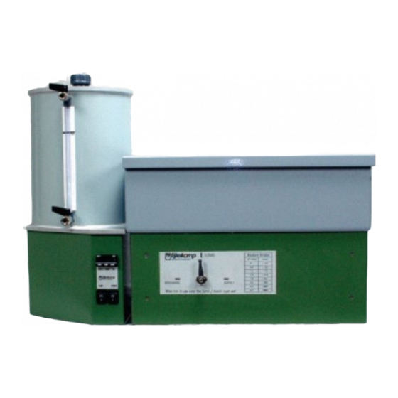
Page 3: Description Of The Sand/Kaolin Box
2 Description of the sand / kaolin box The sand/kaolin box (1) stands on four feet (2) and has a drainage system (4) inside it. This box (1) is filled with very fine synthetic sand, which is covered by a layer of kaolin clay (Kaolinite - also known as china clay). - Page 4 Figure 1: Assembled Sand/kaolin box with numbered components Tap B Tap C Tap A Tap A Tap D 1. Box 9. Throttle valve 2. Box Stand 10. Display 3. Lid 11. Power switch 4. Drainage Pipe 12. Pump switch 5. Vacuum vessel 13.
-
Page 5: Assembling The Sand/Kaolin Box
Assembling the sand / kaolin box All of the tubes are connected and tested for leakage before delivery. Take care not to break the tube connections while unpacking. Check that the intended electrical supply has the correct voltage (230 V). Construct the sandbox using the following instructions (Numbers refer to Figure 1): 4.1 Set up the sand / kaolin box: 4.1.1. -
Page 6: Check The Setup Values
Check the Setup Values The Display (10 see figure 1 on page 4) facilitates access to a lot of extra programming functions that should never be altered. Only adjust the settings referred to in this manual. Table 1: First Menu 4.2.1. - Page 7 4.2.7. After all of the Setup Names have the First Setup Values (Table 2) then use the “Scroll ‘FiLt’ Key” to return to the Setup Name. 4.2.8. Push the “Up-key” and “Down-key” simultaneously (for about 3 seconds) to exit the second menu. The yellow L.E.D will automatically turn off.
-
Page 8: Prepare The Drainage System
Prepare the Drainage System The plastic drainage pipe (4) inside the box (1) must be covered with filter cloth. The supplied filter cloth has two layers, and is 6 cm wide. The plastic drainage pipe needs top be covered by 3 layers of cloth, so that sand wont block the holes in the pipe when suction is applied, and the suction is diffused. -
Page 9: Removal Of Air-Bubbles
4.4 Removal of air-bubbles 4.4.1. Boil 10 L of demineralised water, and leave it to cool. 4.4.2. Open the Cap (6) of the Vacuum Vessel and Fill the Vacuum Vessel up to the ‘Max’ line with this water. (This maximum is visible on the tube between Tap B and Tap C). - Page 10 4.4.7. When there are no air bubbles in the tube between the Drainage Pipe (4) and Tap D then close Tap D. 4.4.8. Tightly close the lid of the Vacuum Vessel (5). (fig 11) Figure 11: Tightly close the lid ...
- Page 11 4.4.9. Check that the Pump is switched off (12: see fig.1 on page 4) and the tap A, B, C and D are closed, then turn the Power on (11: see fig.1 on page 4). Fig.14 pump is off now. 4.4.10.
-
Page 12: Laying The Suction Material
Laying the suction material 4.5.1 Saturate some synthetic sand with running demineralised water and stir firmly to remove air (Fig. 16). There should be a high ratio of water to sand so that it can be easily poured into the box.(fig17) For the textural composition of the sand see Table 3. - Page 13 4.5.4 Stop adding the saturated sand when the sand level is 8 cm below the rim of the Box (1). Always ensure the water level in the Vacuum Vessel (12) is higher than the water level in the Box (1). ‘Supply’...
- Page 14 When using the pump, the water level in the Vacuum Vessel must be checked constantly (See Caption 1). The pressure set-point for the Vacuum Vessel can now be set for flushing the sand / kaolin suction medium. 4.5.13 Check that the pump is switched off (12), and the taps A, B, C and D are closed.
- Page 15 The sand/kaolin suction medium will now be flushed for a few hours to remove the final air-residues, and bond the sand and clay layers. 4.5.20 Press the kaolin clay firmly against the walls of the box, especially in the corners, to prevent air-leakage.(fig25) 4.5.21 Smooth the surface of the kaolin layer level with a clean ruler.
- Page 16 4.5.28 Cut the filter cloth to the correct size by tracing around the lid of the box (1). 4.5.29 Saturate the filter cloth with water in a beaker, before placing it onto the surface of the kaolin layer. (fig 28) 4.5.30 Remove any air bubbles between the filter cloth and the kaolin by gently smoothing it from the centre outwards.
-
Page 17: Using The Sand/Kaolin Box
Using the sand/kaolin box The environment around the sand/kaolin box should be kept at a constant temperature between measurements, since temperature changes affect water viscosity and therefore water retention values. Prepare the Samples 5.1.1. Uncap the core sample ring. If the sampled soil volume is larger than the volume of the core ring, carefully remove excess soil by ‘chipping’... - Page 18 5.1.6. Gently pour demineralised water onto the kaolin surface with the aid of a ruler. Raising the water level to quickly may entrap air in the samples or damage the soil structure. 5.1.7. Stop adding water when the water level is 1cm below the top of the sample ring.(fig 32) 5.1.8.
- Page 19 5.1.11. Place each sample ring at its designated position on the kaolin surface. Press the ring slightly, to improve soil - kaolin contact.(fig 5.1.12. Ensure that the Pump is switched off. 5.1.13. Check that the electrical supply is plugged in and the power (11) is turned on.
-
Page 20: Set Offset Value
5.2 Set Offset Value This section details how the neutral point for the electronic vacuum regulator is corrected during use. If you are in the First Menu with Tap B open, and the PrOC parameter value is not zero, then the atmospheric pressure has changed. To correct this, execute the following steps: Table 4: First Menu 5.2.1. -
Page 21: Calculate Set-Point
Calculate Set-point The rising water level in the vacuum-vessel has no effect on the real pressure applied to the sample, because of the use of an internal filling tube. This water column has a known height. The total water column can be calculated as follows: Total Water Column = H - 85 Figure 37: Total Water Column Calculation... -
Page 22: Changing The Set-Point (Suction To Be Applied To The Samples)
Changing the Set-point (Suction to be applied to the samples) The Display (10) allows access to many extra programming functions that should never be altered. Only adjust the settings referred to in this manual. Figure 8: Display Table 8: First Menu 5.4.1 Check that the power is on (11) and the pump is switched “off”... - Page 23 5.4.7 If necessary then remove excess water from the Vacuum Vessel by following steps 4.5.16 – 4.5.19. 5.4.8 Ensure Taps A, B, C and D are closed. 5.4.9 Turn on the pump (12) 5.4.10 Wait until the relevant pressure has been “Discharge”...
- Page 24 5.4.16 Replace the soil samples on the kaolin at exactly the same position as they were previously. 5.4.17 Repeat steps 5.14 to 5.28 until weights have been recorded at each potential increment (Set-point) you want to measure. Always replace the samples on the clay before changing the pressure...
-
Page 25: Filling In As Measurements Are Taken
6 Table 9: to be filled in as measurements are taken. -
Page 26: Ending A Measurement
7 Ending a measurement Care should be taken to preserve the kaolin layer in the sand/kaolin box when it is not in use. Upon completion of a measurement at, for example, –500 hPa the pressure in the sand and kaolin layer will not decline as quickly as that in the vacuum vessel. Considering this fact, it is recommended that a pressure of about -100 hPa be maintained with the pump remaining on, so that the vacuum in the suction medium equilibrates more gradually. - Page 27 7.11. Turn the pump on to reinstall the previously applied pressure (-100hPa). 7.12. Switch Tap A to supply.(fig 44) Figure 44: Tap A to supply The kaolin/sand box must be stored using one of the following methods: a. Keep the pump switched off. The kaolin layer will soften. Maintain a 2 mm deep layer of water above the surface of the kaolin.
-
Page 28: Processing The Results
Processing the results 8.1. Now it is necessary to determine the dry weight of ring + cloth + elastic (weight C).(fig 45,46) 8.2. Take the elastic-band/off each sample and number it for weighing later 8.3. Transfer the rings (with the samples and Figure 45: weigh the cloth cloths) to an oven, and dry for at least 48 hours at 105 °C. - Page 29 8.9. Determine the dry bulk density ‘ρ ’ (g/cm ) by: 8.10. If the density of the soil water is assumed as 1 g/cm³, then the volumetric soil water content (cm³/cm³) is determined as : 8.11. Plot the calculated volumetric soil water content at the X-axis and the corresponding pF-value on the (positive) Y-axis.
-
Page 30: Troubleshooting
9 Troubleshooting Problem Possible Cause Solution Air in the tube between the There are air bubbles in the De-aerate the tube. supply bottle and the suction water. regulator causes inaccuracy of There’s not enough sand on Add more water-saturated measurements. the drain. -
Page 31: References And Literature
Nothing in this publication may be reproduced and/or made public by means of print, photocopy, microfilm or any other means without previous written permission from Eijkelkamp Agrisearch Equipment. Technical data can be amended without prior notification. Eijkelkamp Agrisearch Equipment is interested in your reactions and remarks about its products and operating instructions. -
Page 32: Appendices
Appendix 2: Description of different pF-sets To determine the soil moisture retention characteristic, the desired pF-set(s) is/are required. A balance with an accuracy of 0.01g, and a ventilated electrical drying oven (105 °C), are also necessary. Eijkelkamp supplies the following: A universal drying-oven with temperature range 30 -220 °C, 220 V- 50 Hz. - Page 33 Ring holders may be used to facilitate insertion, especially in the subsoil. After insertion to the desired depth, the rings are carefully dug out (e.g. using the spatula provided with the Eijkelkamp sample ring set), at some centimeters below the ring itself. The surplus of soil is reduced to a few millimeters, trimming it carefully with a fine iron saw, and the caps are placed on the ring for protection and to minimize evaporation losses.
- Page 34 Declaration of Conformity Declaration de Conformité Konformitätserklärung We / Nous / Wir Eijkelkamp Agrisearch Equipment, 6987 EM Giesbeek declare under our sole responsibility that the product déclarons sous notre seule responsabilité que le produit erklären in alleiniger Verantwortung, dass das Produkt 08.02 Sand / kaolin box...
Need help?
Do you have a question about the 08.02 SAND / KAOLIN BOX and is the answer not in the manual?
Questions and answers