
Related Manuals for EIJKELKAMP 0801

Summary of Contents for EIJKELKAMP 0801
- Page 1 Sandbox for pF-determination User manual Meet the difference Eijkelkamp Soil & Water +31 313 880 200 Nijverheidsstraat 30, 6987 EM info@eijkelkamp.com © 2019-01 M-0801E Giesbeek, the Netherlands www.eijkelkamp.com...
-
Page 2: Table Of Contents
References and literature ..............................25 Nothing in this publication may be reproduced and/or made public by means of print, photocopy, microfilm or any other means without previous written permission from Eijkelkamp Soil & Water. Technical data can be amended without prior notification. Eijkelkamp Soil & Water is not responsible for (personal) damage due to (improper) use of the product. Eijkelkamp Soil & Water is interested in your reactions and remarks about its products and operating instructions. -
Page 3: On These Operating Instructions
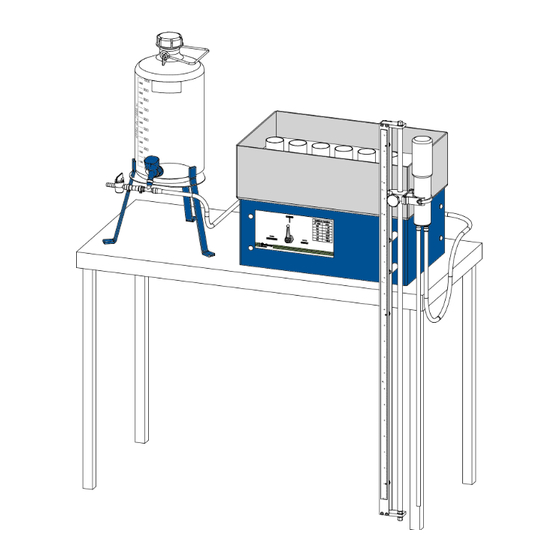
Introduction This Sandbox (acc. to ISO 11274) (art. no.: 0801) can be used to apply a range of pressures from pF 0 (saturation) to pF 2.0 (-100 hPa). Sand is used to convey the suction from the drainage system to the soil samples. The surface of the sand is flexible, which makes it easier to restore the contact between it, and the samples, after they have been removed for weighing. -
Page 4: Technical Specifications
Technical specifications Item Specification Soil sample rings (Ø 53mm) Max. 40 Dimensions of the box on its stand (excl. supply bottle etc.) 55.0 x 33.5 x 37.5 cm (l x w x h) 0 hPa - 100 hPa Operating range 0 bar - 0.1 bar pF 0 –... -
Page 5: Assembling The Sandbox
Assembling the sandbox If the sandbox is already assembled then skip to Chapter 5. All of the tubes are connected and tested for leakage before delivery. Take care not to break the tube connections while unpacking. Construct the sandbox using the following instructions (numbers refer to Figure 1). Before setting up the sandbox Before the sandbox is assembled, the plastic drainage pipe (4) inside the box (1) must be covered with filter cloth. The supplied filter cloth has two layers, and is 6 cm wide. The plastic drainage pipe needs to be covered... - Page 6 4. Saturate the filter cloth in demineralised water (Fig. 4). Fig. 4 Saturate the filter cloth 5. Tie the filter cloth to one end of the drainage pipe - where it enters the inside of the box. 6. Coil the filter cloth around the drainage pipe so that each consecutive winding covers two thirds of the width of the previous one. This will ensure that the entire pipe is covered by three layers of filter cloth (Fig. 5).
-
Page 7: Setting Up The Sandbox
Setting up the sandbox 1. Select a completely level, vibration free table that is at least 1.0 m high. Vibration may cause a leak between the sidewalls of the box and the sand. 2. Place the sandbox on this table, with tap A facing the front Fig. - Page 8 7. Connect the supply bottle (6) to tap A with the supply pipe from the back of the box. Leave tap A ‘Closed’ (Fig. 10). Tap A (back) You may add (0.01 mg/l) copper sulphate to reduce microbiological activity The water level in the supply bottle should not be ...
- Page 9 11. Open tap D, at the back of the box (green) and allow some water to flow from the box (1) into a beaker (Fig. 13). The water level in the box (1) should never fall below the plastic drainage pipe. Tap D 12. When there are no bubbles left between tap B and tap D, close tap D while leaving tap B open.
- Page 10 17. Turn tap A to the ‘Closed’ position. 18. Leave tap B on so that water runs out of tap C when you Tap C open it. Let some water out of tap C to remove the final air bubbles (Fig. 16). There must be no air-bubbles in the system from this point onwards.
- Page 11 21. The sand should be pressed against the side walls of the sandbox, and into the corners, to make sure that the sand does not contain air pockets and a good seal between sand and box is established (Fig. 20). Fig.
- Page 12 26. Turn Tap A to the ‘Supply’ position, and open Tap B. Water from the supply bottle will now flow through the drain and remove final air residues. Each time air appears to be entrapped, the above described procedure is repeated to water remove it. (Fig. 25). Flow ↑ Saturated sand ↑ Flow ...
-
Page 13: Using The Sandbox
Omega ruler (sand 2.5 cm surface). Sand surface The sandbox (art. no. 0801) is now ready to use. Fig. 28 End-on view of Omega ruler For instructions on how to use the sandbox please see Chapter 5. Using the sandbox ... - Page 14 4. Ensure that a 0.5 cm layer of water is covering the surface of the sand in the sandbox (Fig. 31). Fig. 31 Retain 0.5 cm water above the sand 5. Place the soil sample with the bottom side down in the sandbox.
- Page 15 9. Mark the rings, and draw a diagram of the box, so that the rings can be replaced in exactly the sample place after removal (Fig. 35). Fig. 35 Mark samples before placing them 10. Take the ring carefully out of the water basin and wipe off any water drops hanging underneath the sample before weighing it (accuracy of balance 0.01 g) (Fig.
- Page 16 14. Gently remove the samples and weigh them (Fig. 39). 15. To check equilibrium, place the sample on the suction table at exact the same place (take care that the contact between sand and sample is restored) and weigh the sample again the next day.
-
Page 17: Table To Be Filled In As Measurements Are Taken
Table to be filled in as measurements are taken... -
Page 18: Troubleshooting
Troubleshooting Problem Possible causes Solution(s) Air in the tube between the 1. There are air bubbles in the 1. Only use the water if it’s calm. supply bottle and the suction water. Let the supply bottle stand still regulator is distorting the for a while before using the water. -
Page 19: Appendix 1: General Information
Appendix 1: General Information The pF-curves plotted below will be used to illustrate the soil physical characteristics that can be deduced from pF-curves. The example soil contains three different soil horizons (each of which has a known pF-Curve). These curves are referred to in Table 3. Table 3: Determining soil characteristics from pF-Curves Physical characteristic Definition and how to determine... - Page 20 Physical characteristic Definition and how to determine Aeration status Volume of available air: porosity minus moisture content. Depending on crop type, a certain ratio between water and air supply is required for optimal crop growth. In the example soil, (A horizon) at a moisture potential of 1000 hPa (pF 3), moisture content is 20%, total pore space is 50%, so the volume of available air is 30%.
- Page 21 Physical characteristic Definition and how to determine Plant available soil water The amount of water between FC and PWP in volume percentage. This value should be used with caution. First, plants will start wilting with subsequent yield losses well before the permanent wilting point. Secondly, plant available soil water is replenished by capillary rise, rainfall and irrigation water.
-
Page 22: Appendix 2: Description Of Different Pf-Sets
Appendix 2: Description of different pF-sets To determine the soil moisture retention characteristic, the desired pF-set(s) is/are required. A balance with an accuracy of 0.01 g, and a ventilated electrical drying oven (105 °C), are also necessary. Eijkelkamp Soil & Water supplies the following: A sandbox for pF determination (pF0 -2.0). -
Page 23: Appendix 3: Conversion Factors
Appendix 3: Conversion factors 100 hPa = 100 cm pressure head = 100 cm water column = 0.1 bar = 0.01 Pa = 0.01 N/m² = 1.45 PSI = pF (10log100) = 2.0 pF value Matric potential Pressure in hPa in bar -0.001 -0.0025... -
Page 24: Appendix 4: Soil Sampling
5 cm and a volume of 100 cm³ are recommended, while in other publications heights of 2 or 3 cm are preferred. Eijkelkamp Soil & Water recommends the use of a 100 cm³ volume core ring, with an inner diameter of 50 mm (outer diameter 53 mm) and a height of 51 mm. -
Page 25: References And Literature
References and literature Klute, A. Water Retention: Laboratory Methods. IN: Methods of Soil Analysis. Part 1. Physical and Mineralogical Methods. 1986. Koorevaar, P., G. Menelik and C. Dirksen. Elements of Soil Physics Developments in Soil Science 13 1983 Reeve, M.J. and A.D. Carter. Water Release Characteristic. IN: Soil Analysis. Physical Methods. K.A. Smith and C.E.
Need help?
Do you have a question about the 0801 and is the answer not in the manual?
Questions and answers