Table of Contents
Advertisement
Quick Links
Advertisement
Table of Contents

Summary of Contents for HANMEY AM60
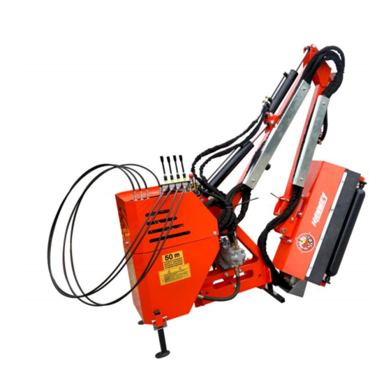
- Page 1 Operate & Parts Manual Hedge cutter AM60/AM80/AM100...
-
Page 2: Table Of Contents
LIST OF CONTENTS SAFETY PRECAUTIONS Page 5 FITTING Page 9 INITIAL ATTACHMENT TO TRACTOR Page 12 FLAILHEAD ATTACHMENT Page 24 REMOVAL FROM TRACTOR Page 25 STORAGE Page 26 OPERATION Page 27 OPERATION GUARD Page 28 MACHINE CONTROLS Page 28 BREAKAWAY Page 29 MOVING INTO THE TRANSPORT POSITION Page 31... - Page 3 READ THE BOOK FIRST It might save hours and pounds later ! When ordering spare parts always quote The Machine Type The Machine Serial Number The Part Number Factory re-built service exchange units of the major hydraulic components are available from your Dealer...
- Page 4 NOISE The equivalent daily personal noise exposure from this machine, measured at the operators’ ear, is within the range 78 – 85 DB. These figures apply to a normal distribution of use where the noise fluctuates between zero and maximum. The figures assume that the machine is fitted to a tractor with a quiet cab with the windows closed in a generally open environment.
- Page 5 GENERAL INFORMATION Read this manual before fitting or operating the machine. Whenever any doubt exists contact your dealer or the McConnel Service Department for assistance. Use only McConnel Genuine spare parts on McConnel equipment and machines. DEFINITIONS The following definitions apply throughout this manual: WARNING An operating procedure, technique etc., which can result in personal injury or loss of life if not observed carefully.
- Page 6 SAFETY INFORMATION...
- Page 7 SAFETY INFORMATION This machine has the potential to be extremely dangerous, in the wrong hands it can kill or maim. It is therefore imperative that the owner, and the operator of this machine, read the following section to ensure that they are both fully aware of the dangers that do, or may exist, and their responsibilities surrounding its use.
- Page 8 ● Ensure flails and their fixings are of a type recommended by the manufacturer, are securely attached and that none are missing or damaged. ● Ensure hydraulic pipes are carefully and correctly routed to avoid damage by chaffing, stretching or pinching and that they are held in place with the correct fittings. Always follow the manufacturer’s instructions for attachment and removal of the ●...
- Page 9 ● Never use a machine if guards are missing or damaged. ● Never use a machine on which the hydraulic system shows signs of wear or damage. Never fit, or use, a machine on a tractor that does not meet the manufacturer’s ●...
-
Page 10: Initial Attachment To Tractor
INITIAL ATTACHMENT TO TRACTOR The machine will be delivered in a partially dismantled condition, secured with transport strap and banding. Choose a firm level site. Remove the transport strap, banding straps and loose items. Raise the machine using overhead lifting equipment with a minimum capacity of 1500kg SWL.... - Page 11 AXLE BRACKET/CATCH ASSEMBLY - FITTING BY DEALER Bolt axle plates to the tractor axle at either 1.0 M or 1.1 M apart - this may necessitate the to removal of the tractor's check chains and/or assister ram brackets, if this is the case, the axle plate will include replacement brackets for these functions.
- Page 12 STANDARD TYPE BRACKETS With the frame in the vertical position, measure dimensions 'A' and 'B', subtract 'B' from 'A' to obtain measurement 'X'. Measure dimension 'C'. Select mounting holes which position the mounting bars in the end of the latch arms so that dimension 'D' equals dimension 'C' minus measurement 'X' and also when the draft link is horizontal and the rocking draft pin is in the upright position dimensions 'E' and 'F' are equal.
- Page 13 ALTERNATIVE TYPE BRACKETS With the frame in the vertical position, measure dimensions 'A' and 'B', subtract 'B' from 'A' to obtain measurement 'X'. Measure dimension 'C'. Select mounting holes which position the mounting bars in the end of the latch arms so that dimension 'D' equals dimension 'C' minus measurement 'X' and also when the draft link is horizontal and the rocking draft pin is in the upright position dimensions 'E' and 'F' are equal.
- Page 14 TRACTOR ATTACHMENT - BY CUSTOMER OR DEALER Reverse tractor squarely into position adjacent to the machine and connect the draft links to the machine - maneuver tractor until both draft pin rockers are vertical. Raise the machine on the tractors linkage sufficient only for the latch bar to fully engage in the axle catch.
- Page 15 Raise the machine on the tractors linkage until the frame is vertical. Fit top link. Measure PTO shaft and cut to dimension shown (distance ‘A’ minus 75mm) - see diagram opposite and refer to maintenance section for further details. NOTE: For subsequent use on a different tractor measure again - there must be a minimum of 6"...
- Page 16 Fit PTO shaft into position. Attach the torque chains to a convenient location to prevent rotation of the shaft guards. Fit machine controls into the cab - refer to the specific page on this subject for further details. FIRST FITTING ONLY - for Dealer reference Request assistance.
- Page 17 Raise the stand legs into the work position and secure with their pins - see diagram opposite. Tighten check chains and/or stabiliser bars. The machine should now be carefully operated throughout its full range of movements to check hoses are not being strained, pinched, chafed or kinked, and that all movements are functioning correctly.
- Page 18 TRACTOR ATTACHMENT – Linkage Mounted Machines With the machine positioned on a firm level site and securely supported, Figure 1 maneuver the tractor squarely up to the machine with the tractor’s draft links set to a height level with the machines lower link brackets....
- Page 19 Fit the machines top link. Figure 4 Fig.4 Raise the machine on the tractors linkage to a position where the tractor PTO and the machines gearbox stub shaft are approximately in line with each other. Note: As lift occurs be aware the machine may tilt slightly.
- Page 20 Fully tighten the stabiliser lower bolts Figure 7 Fig.7 Measure the PTO shaft and cut to the dimension shown – the finished length of the PTO shaft should be 75mm (3”) less than the measured distance ‘A’ - between tractor shaft and gearbox stub shaft - to enable fitting....
- Page 21 On semi independent machines only connect up the supply and return hoses. Supply – from tractors auxiliary service. Return – to tractors transmission casing (refer to Tractors Handbook). Figure 10 Fit the machine control unit into the tractor cab – see page 28 Note: On semi independent machines only select tractors external services.
-
Page 22: Flailhead Attachment
FLAILHEAD ATTACHMENT Operate machine controls to manoeuvre into a position to enable attachment of the flailhead – the bottom of the hose junction bracket must be parallel with the ground. Refer to ‘Pre operational checks’ for correct bolt torque settings. Connect up flail hoses as indicated below. -
Page 23: Removal From Tractor
REMOVAL FROM TRACTOR DANGER READ CAREFULLY BEFORE COMMENCING TO REMOVE THE MACHINE FROM THE TRACTOR. THE ORDER OF THE FOLLOWING STEPS MUST BE FOLLOWED EXACTLY DISCONNECTING THE TOP LINK MUST BE THE LAST OPERATION PRIOR TO DRIVING THE TRACTOR AWAY FROM THE MACHINE. WARNING Do not operate quadrant lever or machine controls through the rear cab window whilst standing on or amongst linkage components. -
Page 24: Storage
STORAGE If machine is to be left standing for an extended period of time, lightly coat the exposed portions of the ram rods with grease. Subsequently this grease should be wiped off before the rams are next moved. If the machine has to be stored outside tie a piece of tarpaulin or canvas over the control assembly, do not use a plastic fertilizer bag which could lead to rapid corrosion. -
Page 25: Operation
OPERATION OPERATOR GUARD PREPARATION READ THE BOOK FIRST Practice operating the machine in an open space without the rotor running until you are fully familiar with the controls and operation of the machine. CAUTION Care must be taken when working with the flail head close in as it can come into contact with the tractor. -
Page 26: Machine Controls
MACHINE CONTROLS Cable controlled machines only... -
Page 27: Breakaway
BREAKAWAY NOTE: The breakaway function does not relieve the operator of his responsibility to drive carefully, be alert and AVOID OBVIOUS HAZARDS BEFORE CONTACT OCCURS. Breakaway may occur momentarily during normal work should an extra thick or dense patch of vegetation be encountered. In these instances tractor forward motion may be maintained with care. -
Page 28: Moving Into The Transport Position
MOVING INTO THE TRANSPORT POSITION Select ‘ROTOR OFF’ and wait until the rotor has stopped turning. Ensure that the ‘lift’ and ‘angle float’ are switched off. Select ‘SLEW’ mode on the control assembly. ... - Page 29 TRANSPORT POSITION – Rear Mounted Machines The machine is transported in line to the rear of the tractor with a minimum of 3OOmm clearance between the tension link and the rear cross member of the tractor cab. TRANSPORT POSITION WITH FLAILHEAD REMOVED With the flailhead removed the arms are fully folded but with the lift ram fully retracted.
-
Page 30: Moving From Transport To Work
TRANSPORT When in transport the P.T.O. must be disengaged and the power to the control box switched off. The acceptable speed of transport will vary greatly depending upon the ground conditions. In any conditions avoid driving at a speed which causes exaggerated bouncing as this will put unnecessary strain on the tractors top hitch position and increase the likelihood of the tension link contacting the cab rear cross member. -
Page 31: Rotor Operating Speed
ROTOR OPERATING SPEED TRACTOR FORWARD SPEED The material being cut determines tractor forward speed. Forward speed can be as fast as that which allows the flail head sufficient time to cut the vegetation properly. Too fast a speed will be indicated by over frequent operation of the breakaway system, a fall off in tractor engine revs and a poor finish to the work leaving ragged uncut tufts... -
Page 32: High Voltage Cables
HIGH VOLTAGE CABLES It cannot be stressed enough the dangers involved when working near high voltage electricity cables. Before attempting to work in these areas ensure you have read and fully understood the safety section at the beginning of this manual which includes information on this subject. - Page 33 HEDGE CUTTING PROCEDURE 1. Cut the side and bottom of the field side first. This leaves the maximum thickness of hedge on the road side to prevent the possibility of any debris being thrown through the hedge into the path of oncoming vehicles.
-
Page 34: Working On Adverse Slopes
WARNING NEVER CUT ON THE BLIND SIDE OF THE HEDGE. It is impossible to see potential hazards or dangers and the position of the flail head would possibly allow debris to be propelled through the hedge towards the tractor and the operator. WORKING ON ADVERSE SLOPES When working high with the reach fully in it is possible for the main arm balance to go over... -
Page 35: Maintenance
MAINTENANCE LUBRICATION GENERAL Grease daily all the points shown in the diagram above. P.T.O. SHAFT Regularly check the P.T.O. guards for damage and ensure the anti rotation chains are in place and that their anchor points are in good condition. Lubricate the points shown on the diagram below at the intervals indicated using general purpose lithium based grease. -
Page 36: Hydraulic System
HYDRAULIC SYSTEM OIL SUPPLY Check the oil level in the reservoir daily. No fixed time period can be quoted for oil changes as operating conditions and maintenance standards vary so widely. Burnt and scorched oil odours and the oil darkening and thickening are all signs of oxidation and indicate the oil should be changed. Moisture that results from condensation can become entrapped in the oil and cannot be removed by filtration so that water contamination is progressive. -
Page 37: Hydraulic Hoses
HYDRAULIC HOSES The condition of all hoses should be carefully checked during routine service of the machine. Hoses that have been chaffed or damaged on their outer casing should be securely wrapped with waterproof adhesive tape to stop the metal braid from rusting. Hoses that have suffered damage to the metal braid should be changed at the earliest opportunity. - Page 38 Article no. Part no. Name&spec 702830121 BH-6.07.091 short hand shank 702910335 MBH-6.08.108 Joystick(short) 503010099 GB6172.1-M10 Thin nut 702770020 AM60.01.120 Shifting block 702770019 AM60.01.119 Protecting bush 505011395 GB70.1-M5X35 hexagon socket cap screw 508010099 GB119.1-B-6X26 B cylindrical pin 702770015 AM60.01.114 Upper cover 702770010 AM60.01.109...
- Page 39 Article no. Part no. Name&spec 702770005 AM60.01.104 bush 510013130 GB3452.1-G-16X2.65 O sealing 702770007 AM60.01.106 Lock shaft 702770004 AM60.01.103 Locating sleeve 702770006 AM60.01.105 Fixed seat 2 702770002 AM60.01.101 Screw rod 702770214 AM60.01.112A Lower cover hexagon socket cap screw 505011393 GB70.1-M5X25 hexagon socket cap screw 505011391 GB70.1-M5X16...
- Page 40 AM mowing part Article no. Part no. Name&spec hexagon locking thin 503010764 DIN985-M14 506010058 GB97.1-14 Plain washer 501011142 GB5783-M14X40 Screw bolt 802770061 AM60.02.017 hitch frame weldment 802770037 AM60.02.010 Hood weldment 802780005 AM80.02.010 Hood weldment 806830004 AM100.02.010 Hood weldment 702770033 AM60.02.110 Head board 702780002 AM80.02.110...
- Page 41 Plain washer 802770055 AM60.02.014 roller shaft seat 1 inner hexagon sunk 505011750 GB70.3-M12X30 screw 501011127 GB5783-M12X35 Screw bolt 51-1 802770207 EFG120.012-AM60 Roller weldment(AM60) 51-2 802780018 EFG120.012-AM80 Roller weldment (AM80) Pulley weldment 51-3 806830008 EFG120.012-AM100 (AM100) 802770058 AM60.02.016 Roller shaft 2...
- Page 42 AM mowing part Article no. Part no. Name&spec 802770115 AM60.03.016 fuel tank cover 703070084 CBW-00-011 Air plug M16X1.5 802770118 AM60.03.017Y-1 Fuel tank 509010012 JB7941.2-B80 Liquid level meter 700920105 EF100.00.117 End cover 703190209 1G-150-01-142 Middle R pin 800920101 EF100.00.111A D square cotter 802770128 AM60.03.018...
- Page 43 Article no. Part no. Name&spec 700080010 200.56.011 Lockpin assembly 802770135 AM60.03.021 Lifting eye weldment 802770138 AM60.03.022 connecting lever weldment 501014279 GB27-M20X95 articulation bolt 703400008 FM120.00.199 PTO shaft cover 506010035 GB96.1-8 Extra large plain washer 506030035 GB93-8 Spring washer 501011098 GB5783-M8X16...
- Page 44 AM mowing part Article no. Part no. Name&spec 501014283 GB27-M20X130 Articulation bolt 802770096 AM60.03.014 Small support arm 506010061 GB97.1-20 Plain washer 503010767 DIN985-M20 hexagon locking thin nut 501014240 GB27-M16X120 Articulation bolt 802770093 AM60.03.013 pushing pull plate 506010059 GB97.1-16 Plain washer...
- Page 45 Article no. Part no. Name&spec 702770071 AM60.03.107 oil tube short cover 505011431 GB70.1-M10X35 Hexagon socket cap screw 702770068 AM60.03.104 buffering limited block 802770108 AM60.03.015 big support arm 702770072 AM60.03.108 oil tube long cover 702770160 AM60.04.023 Smaller arm cylinder 702770152 AM60.04.015...
- Page 46 503010761 DIN985-M8 hexagon locking thin nut 702770173 RFA-100X30L Return oil filter 706530042 1CM-18WD M18X1.5(both end)adapter 510015250 JB982-42 Bonded washer M42 702770147 AM60.04.104-1 Oil filter adapter 703070084 CBW-00-011 Air plug M16X1.5 510015240 JB982-16 Bonded washer M16 702930505 MBH-8.08.117 Fuel tank cap...
- Page 47 501011087 GB5783-M6X12 Screw bolt 506030034 GB93-6 Spring washer 506010054 GB97.1-6 Plain washer 702770323 DC6DV1 Single valve 702770330 AM60.04.107 oil pump inlet tube 25-1 702770305 AM60.04.105 Joimt (on big pump) 25-2 510013139 GB3452.1-G-23.6X2.65 O sealing ring 25-3 705190067 1CB-18-08WD Transition connector M18X1.5-...