1 Safety Precautions 1.1. General Guidelines 1.3. Leakage Current Hot Check (See Figure 1.) IMPORTANT SAFETY NOTICE There are special components used in this equipment 1. Plug the AC cord directly into the AC outlet. Do not use which are important for safety. These parts are marked an isolation transformer for this check.
2 Warning 2.1. Prevention of Electrostatic Discharge (ESD) to Electrostatically Sensitive (ES) Devices Some semiconductor (solid state) devices can be damaged easily by static electricity. Such components commonly are called Electrostatically Sensitive (ES) Devices. Examples of typical ES devices are IC(integrated circuits)and some field-effect transistors and semiconductor “chip”...
If you lose the fuse cover, the plug must not be used until a replacement cover is obtained. A replacement fuse cover can be purchased from your local Panasonic Dealer. If the fitted moulded plug is unsuitable for the socket outlet in your home then the fuse should be removed and the plug cut off and disposed of safety.
2.3. Precaution of Laser Diode CAUTION : This product utilizes a laser diode with the unit turned “on”, invisible laser radiation is emitted from the pick- up lens. Wave length:770 to 800 nm (CDs)/645 to 660 nm (DVDs) Maximum output radiation power from pick-up:100 μW/VDE Laser radiation from the pick-up lens is safety level, but be sure the followings: Do not disassemble the optical pick-up unit, since...
2.4. Static Electricity Protection Measures • The laser diode in the traverse unit (optical pick-up) may break down due to potential difference caused by static electricity of clothes or human body. So, be careful of electrostatic breakdown during repair of the traverse unit (optical pick-up). 2.5.
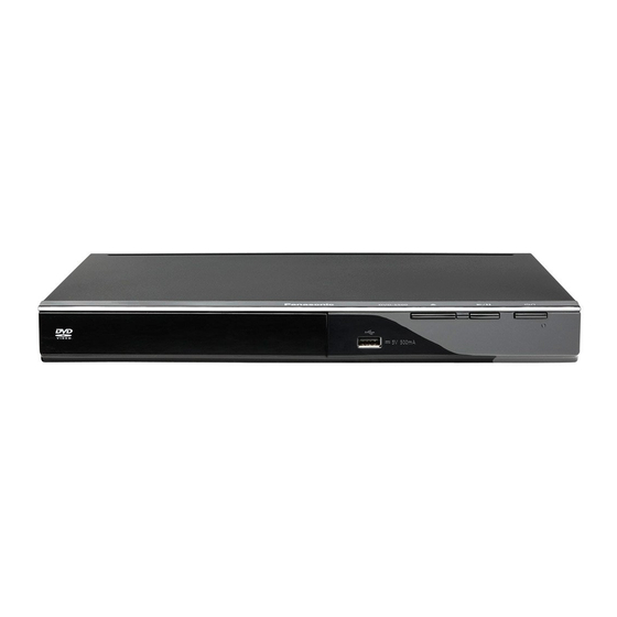
3 Service Navigation 3.1. Service Information This service manual contains technical information, which allow service personnels to understand and service this model. Please place orders using the parts list and not the drawing reference numbers. If the circuit is changed or modified, the information will be followed by service manual to be controlled with original service manual.
3.3. How to Update Firmware The firmware of the DVD player may be renewed to improve the quality including operational performance and playability. Make sure to refer the following procedure when performing version-up. Step1 Check the software version currently installed in your DVD player. 1.
4 Specifications Video output: AC 220 to 240 V, 50 Hz Power supply: Output level 1.0 Vp-p (75 Ω) Approx. 10 W Power consumption: Output connector: Pin jack (1 system) Power consumption in standby mode: Less than 1W HDMI AV Output: 310(W) x 210(D) x 39(H) mm Dimensions: (DVD-S700 only)
Panasonic has no authority to and does not grant you that permission and explicitly disclaims any right, ability or intention to obtain such permission on your behalf.
5 Location of Controls and Components SETUP Enters or exits the system setup menu RETURN Returns to the previous display SKIP, f, e • Skips to previous title/chapter/track or next title/chapter/track • Switches the MENU page of VCD equipped with Playback Control (PBC) function SEARCH, d, c Starts fast reverse or fast forward STOP n , n...
6 Operating Instruction 6.1. Take out the Disc from Drive Unit when the Disc cannot be ejected by the OPEN/CLOSE button 6.1.1. When the Disc Eject can not be done. 1. Turn off the power and pull out AC cord. 2.
7 Troubleshooting Guide 7.1. About Operation of Set To reset Images from this DVD player do not appear on the television. You forget your password. ⇒Reset the DVD player to the factory defaults. 1) Press z/ on the DVD player to turn it on. 2) Press OPEN/CLOSE q to open the disc tray.
7.2. About Circuit Symptom -1 Symptom -2 Can not OPEN or CLOSE No power Check the OPEN/CLOSE SW. Exchange the Check the AC cord. Exchange the (Break or click feeling ...etc.) Power supply P.C.B. (cutting or damage…etc.) AC cord Check the Check the Digital P.C.B.
Page 16
Symptom -3 No Picture, No sound Check the Check the Item-2, Disc tray Operation. afterwards check (OPEN and COLSE) the Item-3 DVD-S500E--XP8 DVD-S700E--XP4 Check the Operation and display. Check the 1.DISC TOC read. Digital P.C.B. connector 2.Track No. and voltage.*3 playback time.
8 Wiring Connection and Voltage Data 8.1. DVD-S500 SCART CVBS POWER MECHANISM SUPPLY UNIT P.C.B. AUDIO VIDEO AMP&LPF LPF &DRIVER USB DM USB DP USB VCC HOME SLED+ MOTOR SLED- SPHE8202R DRIVER Powerkey AM5890S DATA TRIN +12V FLASH SDRAM DIGITAL P.C.B. DVD-S500 VOLTAGE DATA (measurement value) REF.NO.
8.2. DVD-S700 SCART HDMI CVBS POWER MECHANISM SUPPLY UNIT P.C.B. AUDIO VIDEO AMP&LPF LPF &DRIVER USB DM USB DP USB VCC HOME SLED- MOTOR SLED+ SPHE8203R DRIVER Powerkey AM5890S DATA SDRAM TRIN +12V FLASH DIGITAL P.C.B. DVD-S700 VOLTAGE DATA (measurement value) REF.NO.
9 Disassembly and Assembly Instructions 9.1. Unit (DVD-S500/S700) 9.1.1. Disassembly Flow Chart The following chart is the procedure of disassembling the casing and inside parts for internal inspection when carrying out the servicing. To assemble the unit, reverse the steps shown in the chart below. Top Panel Front Panel Power Supply P.C.B.
Page 20
9.1.3. Top Panel 3. Remove the Front Panel. 1. Remove the 2 Screws (A). 2. Expanded the both ends of the back of the top panel in the direction of arrow (1), and then remove it by pulling up in the direction of arrow (2). Top Panel Front Panel Screw (A)
Page 21
9.1.6. Digital P.C.B. 9.1.7. Mechanism Unit 1. Remove the FFC. 1. Refer to 9.1.5 to remove the Power Supply P.C.B.. 2. Remove the Wire with Connector (B) and the Wire 2. Remove the FFC. with Connector (C). 3. Remove the Wire with Connector (B) (6P). 3.
10.3. Replacement Parts List Notes: *Important safety notice: Components identified by mark have special characteristics important for safety. When replacing any of components, be sure to use only manufacture’s specified parts shown in the parts list. *All parts are supplied by PAVCJM. Ref.