
Related Manuals for Sony VPL-V800Q


Summary of Contents for Sony VPL-V800Q
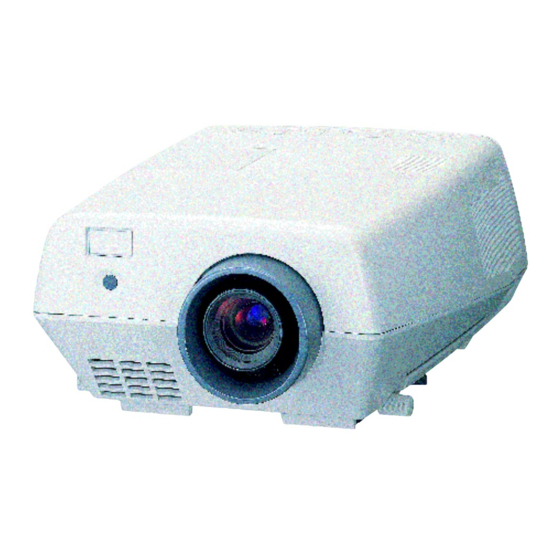
- Page 1 3-858-857-11(1) LCD Data Projector Operating Instructions VPL-V800Q VPL-V800QM © 1997 by Sony Corporation...
- Page 2 English WARNING To prevent fire or shock hazard, do not For the customers in the United Kingdom expose the unit to rain or moisture. WARNING THIS APPARATUS MUST BE EARTHED To avoid electrical shock, do not open the cabinet. Refer servicing to qualified IMPORTANT personnel only.
-
Page 3: Table Of Contents
Table of Contents Overview Precautions ..............4 (EN) Features ..............6 (EN) Location and Function of Controls ......7 (EN) Setting up and projecting Installing the Projector ........... 16 (EN) Connecting with a Computer or a VCR ....17 (EN) Projecting .............. -
Page 4: Precautions
• Do not place your hand or objects near the ventilation holes — the air coming out is hot. On installation • When the projector is mounted on the ceiling, the Sony PSS-800 Projector Suspension Support must be used for installation. • Allow adequate air circulation to prevent internal heat build-up. Do not place the unit on surfaces (rugs, blankets, etc.) or near materials (curtains,... - Page 5 On preventing internal heat build-up • After turning off the power, the cooling fan runs for about two minutes while the POWER indicator flashes in green. The indicator flashes quickly for the first minute. During that time, you will not be able to turn the power back on with the POWER ON key.
-
Page 6: Features
The projector has the RS-422A interface connectors for communication. By combining the optional IFB series interface boards and signal interface switcher, VPL-V800Q/QM projection system can be greatly expanded. This projector also has an index function for using multiple projectors in one system. -
Page 7: Location And Function Of Controls
Location and Function of Controls Front !£ !™ !¡ !º 1 Remote Commander pocket 8 Handle lever Houses the supplied Remote Commander. When Use the lever for putting away the carrying handle. inserting the Remote Commander, make sure the 9 Carrying handle infrared transmitter is facing forwards and push it until it clicks. - Page 8 Location and Function of Controls Using the carrying handles Using the adjusters Pull out to use for carrying the projector. To put away the handle, slide the handle lever backward. To raise To lower the projector the projector When turning the screw counterclockwise, the adjuster comes out.
- Page 9 Control panel !¶ !§ !∞ !¢ !£ !™ !¡ !º MUTING VOLUME LENS CONTROL INPUT SELECT POWER PICTURE MEMORY MENU SHIFT ZOOM FOCUS PATTERN VIDEO LIGHT STANDBY u – – – – AUDIO RESET ENTER SELECT VIDEO/S VIDEO 1 POWER keys Note ON : Press to turn on the power when the projector is When the lamp is warm, it may not light up easily.
- Page 10 Location and Function of Controls 8 FOCUS +/– keys Adjusts the focus. + : Picture focuses forward. – : Picture focuses farther back. 9 ZOOM +/– keys Adjusts the zoom. + : Picture size is enlarged. – : Picture size is reduced. 0 SHIFT +/–...
- Page 11 Set the index number of the projector when using 4 CONTROL S IN/OUT jacks (stereo minijack) multiple projectors. You can set the numbers between Connect to the control S jacks of other Sony “01” and “99”. It is set to “01” at the factory. equipment.
- Page 12 OUT (mini DIN 4-pin): Used as loop-through output For details on installing the interface boards, consult with via the Y/C IN connectors or the IN connector. qualified Sony personnel. Indicator (red): Lights up when the REMOTE 1 IN Note connector is selected.
- Page 13 Remote Commander The Remote Commander can be used as a wireless or If you use the optional RM-PJ20/PJ21 Mouse wired Remote Commander. The functions of the keys Receiver, you can use the Remote Commander as a on the Remote Commander are the same as those on mouse for a connected computer.
- Page 14 Location and Function of Controls 6 VOLUME +/– keys 7 MENU key 8 ENTER keys SECOND 9 Joy stick Used to move the on-screen cursor or to make various Designate the input from the switcher. adjustments. 0 RESET key When the SWITCHER/INDEX/LENS selector is set to INDEX !¡...
- Page 15 • The remote control detectors on the projector do not Battery installation operate when connecting the remote commander cable to the CONTROL S IN jack. If you wish to use Push and slide to open the lid. the Remote Commander as a wireless Remote Commander, be sure to remove the remote commander cable from both the Remote Commander and the projector.
-
Page 16: Installing The Projector
Installing the Projector This section describes the installation arrangements for installing the projector on a table. For ceiling installation, consult with qualified Sony personnel (see page 36 (EN)). Horizontal center Install the projector so that the tip of the lens is of the screen within this area. -
Page 17: Connecting With A Computer Or A Vcr
Connecting with a Computer or a VCR This section describes how to connect the projector with a computer, VCR, and external active speakers. For details on how to connect other equipment, see pages 37 (EN) to 39 (EN). Also refer to the instruction manuals of the equipment to be connected. When making connections, be sure to: •... -
Page 18: Projecting
Projecting STANDBY indicator POWER indicator Rear remote control detector Front remote control detector MUTING VOLUME LENS CONTROL INPUT SELECT POWER PICTURE MEMORY MENU SHIFT ZOOM FOCUS PATTERN VIDEO LIGHT MAIN POWER – – – – STANDBY u – – – –... - Page 19 Switch on equipment connected to the projector. Press the INPUT SELECT keys on the Remote Commander or the control panel to select the input source. VIDEO: Selects the video signal input from the VIDEO or S VIDEO connectors and the audio signal input from the AUDIO IN L/R jacks.
- Page 20 Projecting Press the SHIFT +/– key on the Remote Commander or the control panel to adjust the vertical position of the picture. “PICTURE SHIFT” appears on the screen during adjustment. Press Adjust the volume the VOLUME +/– keys. Cut off the sound the AUDIO MUTING key (also cut off the signal output from the AUDIO OUT jacks.) To restore the sound, press the...
-
Page 21: Using The Menu
Using the MENU To clear the menu display The projector is equipped with an on-screen menu for making various adjustments and settings. Adjustable Press the MENU key. The menu display also items are displayed in green. disappears automatically if no key is pressed for one To select the language used in the menu, see page minute. -
Page 22: The Input Select Menu
The INPUT SELECT Menu The INPUT SELECT menu is used for selecting the INPUT-A input signal. Selects audio and video signals input from the INPUT V I D E O A connectors. V I D E O : V I D E O INPUT SELECT I N P U T - A... -
Page 23: The Picture Audio Ctrl Menu
The PICTURE AUDIO CTRL Menu The PICTURE AUDIO CTRL menu is used for CONTRAST adjusting the picture and volume. Adjustable items are displayed in green. Adjusts the picture contrast. V I D E O C O N T R A S T INPUT SELECT B R I G H T... - Page 24 The PICTURE AUDIO CTRL Menu D. (Dynamic) PICTURE Items that cannot be adjusted depending on the types of input signal Emphasizes the black color. Item Cannot be adjusted with V I D E O C O N T R A S T INPUT SELECT B R I G H T...
-
Page 25: The Input Setting Menu
The INPUT SETTING Menu The INPUT SETTING menu is used to adjust the input • When changing the setting: Press the V or the v key to change the setting and signal. Adjustable items are displayed in green. press the B or the ENTER key. <page 1>... - Page 26 The INPUT SETTING Menu SHIFT CLAMP Adjusts the position of the picture. Corrects the luminance of the picture. I N P U T - A D O T P H A S E : 6 4 INPUT S I Z E SELECT H : 8 0 0 V : 1 5 6...
- Page 27 SIG PROCESS Selects the conversion format from the frame format or field format when the signal is input. I N P U T - A C O L O R T E M P : H I G H INPUT SELECT S I G P R O C E S S : F R A M E F I E L D...
-
Page 28: The Set Setting Menu
The SET SETTING Menu 2. Adjust an item The SET SETTING menu is used for changing the set • When changing the adjustment level: settings of the projector. Adjustable items are To increase the number, press the V or the b key. displayed in green. - Page 29 STATUS (on-screen display) Adjust the focus with the V, v or the b, B key. On the Remote Commander, move the joy stick up, Sets up the on-screen display. down or to the right, left. I N P U T - A F O C U S INPUT SELECT...
- Page 30 The SET SETTING Menu INPUT-A LANGUAGE Selects the RGB or component signal input from the Selects the language used in the menu and on-screen INPUT A connectors. displays. I N P U T - A I N P U T - A F O C U S S P E A K E R : O N INPUT...
- Page 31 INDEX Displays the index number set with the INDEX switches on the rear of the projector. I N P U T - A S P E A K E R : O N INPUT L A N G U A G E : E N G L I S H SELECT H P O L A R I T Y : N O R M A L PICTURE...
-
Page 32: The Input Info Menu
The INPUT INFO Menu The INPUT INFO menu displays the information on a SonG current input signal. Indicates the polarity of the Sync on Green. When the I N P U T - A picture is being projected using its sync signal, NEG is f H : 3 1 . - Page 33 Memory Preset signal fH(kHz) fV(Hz) Sync PC 9801 32.84 H-neg V-neg Indicates the memory number of the current input High resolution signal. SONY News-1 63.337 59.978 Sync on G Memory Preset signal fH(kHz) fV(Hz) Sync SONY News-2 63.337 59.978 H-neg V-neg Sun micro 61.8 65.96...
-
Page 34: Installation Examples
Installation Examples When you install the projector, be sure to adjust the horizontal positioning of the projector so that the lens is aligned with the horizontal center of the screen. Top view Center of the unit 56 mm inches) Center of the screen Center of the lens (EN) -
Page 35: Floor Installation
Floor Installation Wall Center of the screen lens 7 mm ( inches) Center of the lens Distance between the tip of the lens hood and the center of the lens Floor a: distance between the screen and the center of the lens b: distance between the floor and the center of the lens c: distance between the floor and the bottom of the projector x: free... -
Page 36: Ceiling Installation
Installation Examples Ceiling Installation When installing the projector on the ceiling, use the For ceiling installation, consult with qualified Sony PSS-800 Projector Suspension Support. personnel. PSS-800 Projector Suspension Support (not supplied) Ceiling Center of the screen Center of the lens... -
Page 37: Connection Examples
Connection Examples For details on how to connect a computer, a VCR or To set the index number external active speakers, see page 17 (EN). Also refer to the instruction manual of the equipment to be You have to set the index number when you use the connected. -
Page 38: Connecting 15K Rgb/Component Equipment
Connection Examples Connecting 15k RGB/Component Equipment 15k RGB/component equipment to RGB/component output BNC cable Rear – – – – CONTROL S REMOTE INDEX TRIG RS-422A PLUG IN POWER to a wall outlet S VIDEO VIDEO AUDIO IN INPUT A Y IN C IN R/R-Y B/B-Y SYNC/HD... -
Page 39: Connecting The Switcher
Connecting the Switcher Use the optional PC-1271 Signal Interface Switcher • Set the INPUT-A item in the SET SETTING menu for connecting various video equipment. The input is depending on the type of external equipment selected by pressing the SWITCHER/INDEX/LENS connected to the INPUT A connectors on the keys on the Remote Commander. -
Page 40: Maintenance
Maintenance Replacing the Lamp Cleaning the Air Filter When it is time to replace the lamp, the message The air filter should be cleaned in every 100 hours. “Please replace the LAMP.” appears on the screen When it becomes difficult to remove the dust from the when you turn on the projector. -
Page 41: Troubleshooting
Troubleshooting If the projector appears to be operating erratically, try to diagnose and correct the problem, using the following guide. If the problem still persists, consult with qualified Sony personnel. Symptom Cause Remedy The MAIN POWER switch is turned off. - Page 42 If the error code is still in the window after the above operation, consult with qualified Sony personnel. The internal circuits do not function Inform the displayed error code to qualified Sony personnel. Others correctly. (EN)
-
Page 43: Specifications
Specifications REMOTE RS-422A Optical characteristics D-sub 9-pin (female) (For details, see “Pin assignment” Projection system 3 LCD panels, 1 lens, projection on page 45 (EN).) system TRIG Minijack, 5 Vp-p LCD panel 1.3-inch TFT LCD panel, Power on: DC 5 V output, 921, 600 pixels (307, 200 pixels impedance more than 4.7 kilohms ×... - Page 44 (w/h/d) SIC Cable Mass Approx. 25 kg (55 lb 2 oz) SIC-10/20A/20C/21/22/30/31/M1/M5/M15/M25/ Power requirements VPL-V800Q: AC 100 to 120 V/220 CCQ-2BRS/5BRS/10BRS/25BRS/50BRS to 240 V, 50/60 Hz 9-pin remote cable (for RS-422A) VPL-V800QM: AC 220 to 240 V, RCC-5G/10G/30G 50/60 Hz...
- Page 45 VPS-100FH (100-inch, flat) VPS-120FH (120-inch, flat) 13 14 14 13 Some of the items may not be available in some areas. For details, please consult your nearest Sony office. Pin assignment Pin No. Signal Signal level RS-422A connector (D-sub 9-pin, female) Ground HD/C.
- Page 46 Specifications Dimensions Front 480 (18 397.5 (15 360 (14 308 (12 Center of the unit 93.5 (3 43 (1 90 (3 56 (2 294 (11 440 (17 Ventilation holes Center of the lens (exhaust) Rear Center of the unit 397.5 (15 293 (11 107 (4 160.5 (6...
- Page 47 480 (18 40 (1 ) 121.5 (4 51.5 (2 Center of projection balance φ138.5 (5 Center of the unit 56 (2 Center of the lens φ131.7 (5 360 (14 Bottom 207.8 (8 168.7 (6 Hole for attaching the PSS-800 Hole for attaching the PSS-800 Ventilation holes (intake) Hole for attaching the PSS-800...
- Page 48 Specifications Side Ventilation holes 322 (12 (right side: intake left side: exhaust) Center of projection balance 207.5 (8 53 (2 Unit: mm (inches) (EN)
-
Page 49: Index
Index I, J, K Adjusters 8 (EN) INDEX 31 (EN) Remote Commander battery installation 15 (EN) Adjusting Index number 11 (EN) the picture 23 (EN) INPUT-A 22 (EN), 30 (EN) connecting to the projector 15 (EN) the picture size/shift 25 (EN), 26 (EN) INPUT-B 22 (EN), 30 (EN) location and function of controls the picture luminance (Clamp Setting)
Need help?
Do you have a question about the VPL-V800Q and is the answer not in the manual?
Questions and answers