Table of Contents

Subscribe to Our Youtube Channel
Related Manuals for Jupiter Avionics JCP3-070

Summary of Contents for Jupiter Avionics JCP3-070
- Page 1 JCP3-070 Control Panel with RX Volume Controls Installation and Operating Manual Rev A Jupiter Avionics Corporation 1959 Kirschner Road Kelowna BC Canada V1Y 4N7 Tel: +1 778 478 2232 Toll-Free: 1 855 478 2232 www.jupiteravionics.com...
- Page 2 All rights reserved Jupiter Avionics Corporation (JAC) permits a single copy of this manual to be printed or downloaded for the express use of an installing agency. Any such electronic or printed copy of this manual must contain the complete text of this copyright notice.
-
Page 3: Table Of Contents
Legend Text Selection using ProCS™ ......................6 Adjustments and Configuration using ProCS™ ....................7 2.6.1 ProCS™ Setup ............................7 2.6.2 Configuring the JRAC-xxx Remote Audio Controller via the JCP3-070 ........... 7 Installation Kit ..............................7 2.7.1 Recommended Crimp tools ........................7 Installation Drawings ............................7 SECTION 3 –... - Page 4 JCP3-070 Control Panel with RX Volume Controls Installation and Operating Manual 3.3.3 Transmitting (Transmit Operation) ......................12 3.3.4 VOX Operation ............................12 ICS Operation 3.3.5 ............................12 Multi-Function (XMIT / ICS) Switch Operation 3.3.6 ..................12 Music Operation 3.3.7 ............................. 13 Emergency Operation Mode ...........................
-
Page 5: Section 1 - Description
JCP3-070 Control Panel with RX Volume Controls SECTION 1 - DESCRIPTION System Overview The JCP3-070 Control Panel with RX Volume Controls is part of an aircraft audio system consisting of one control panel and one remote audio controller. Figure 1-1 Aircraft Audio System The JCP3-070 has the switches and level controls that allow the user to operate the remote audio controller. -
Page 6: Inputs And Outputs
JCP3- 070 Contro ol Panel wit th RX Volum me Controls Installation and Opera ting Manua Inputs a nd Output Refer to the J CP3-070 nnector maps for the matin g connector d designators a and pin assign nments for the nput and outp put signals. -
Page 7: Mechanical Specifications
JCP3-070 Control Panel with RX Volume Controls Installation and Operating Manual Rated Input Level Music rated input 400 mVrms ±10% Rated Output Power Music rated output level 400 mVrms ±10% Output Load Music load 1000 Ω ±10% 1.4.1.4 Discrete Signals Active low control input, active signal level ≤... -
Page 8: Section 2 - Installation
Introduction This section contains unpacking and inspection procedures, installation information, and post-installation checks. Continued Airworthiness Maintenance of the JCP3-070 is on condition only. Scheduled inspection and/or periodic maintenance of this unit is not required. Unpacking and Inspecting Equipment Unpack the equipment carefully. Check for shipping damage and report any problems to the relevant carrier. Confirm that the Authorized Release Certificate or Certificate of Conformance is included. -
Page 9: Mechanical Installation
2.4.3 Mechanical Installation The JCP3-070 can be mounted in any attitude and location with adequate space for the front panel and sufficient clearance for the connector and wiring harness. It requires no direct cooling. 2.4.4 Legend Replacement The JCP3-070 illuminated legends are field replaceable. -
Page 10: Legend Text Selection Using Procs
The configuration program ProCS™ can be used to customize the text for each legend either at the time of ordering the unit, or if text changes are required after installation. The JCP3-070 need not be connected to a computer to select the legend text. -
Page 11: Adjustments And Configuration Using Procs
ProCS Setup - JA99, ProCS Setup - CAB-USB-0006 and ProCS Setup - Virtual Panel show the connections used for testing the JCP3-070. These setup drawings would not be used in normal operation. ProCS Setup - JRAC-001 shows the cabling for using the JCP3-070 for configuring the JRAC Remote Audio Controller using ProCS™ (see section 2.6.1 above). -
Page 12: Section 3 - Operation
This section contains the operating instructions for the JCP3-070. The JCP3-070 acts as a Control Panel for a remote audio controller such as the Jupiter Avionics JRAC-001. The JCP3-070 commands the remote audio controller, and this manual is written to describe the results of any operation of the JCP3-070 controls. -
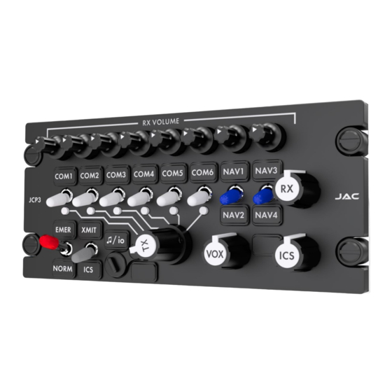
Page 13: Individual Receive Volume Controls
JCP3-070 Control Panel with RX Volume Controls Installation and Operating Manual Individual Volume Controls These are eight non-illuminated rotary controls, each of which is associated with the COM or NAV switch below it. Rotating a control clockwise (cw) will increase the volume of the associated radio, and rotating it counterclockwise (ccw) will reduce it. -
Page 14: Multi-Function (Transmit/Ics) Switch
JCP3-070 Control Panel with RX Volume Controls Installation and Operating Manual Multi-function (Transmit/ICS) Switch This is a green two-position centre-off momentary toggle switch. When in the default XMIT/ICS configuration, this switch acts as the pilot’s ‘Press-to-talk’ (PTT) button. The unit will transmit on the selected transceiver when the switch is held in the ‘up’... -
Page 15: Transmit Selector
JCP3-070 Control Panel with RX Volume Controls Installation and Operating Manual Transmit Selector This is a rotary six-position control that is used to select transmission via one of the six transceivers. Each of the transmit selector positions is linked by a white line to the corresponding transmit select annunciator, transceiver switch and legend. -
Page 16: Normal Operation Mode
JCP3-070 Control Panel with RX Volume Controls Installation and Operating Manual Normal Operation Mode Note: Numbers in parentheses refer to the front panel controls shown in section 3.2. The Audio System is in Normal mode when the front panel EMER / NORM switch (5) is in the NORM position and suitable electrical power is supplied to the audio system (Control Panel with RX Volume Controls, and Remote Audio Controller). -
Page 17: Music Operation
JCP3-070 Control Panel with RX Volume Controls Installation and Operating Manual 3.3.6 Multi-Function (XMIT / ICS) Switch Operation Note: At installation, this switch may be configured to operate in default or alternative mode. Check with your installing agency for confirmation of the operation of this switch. -
Page 18: Appendix A - Installation Drawings
Appendix A - Installation Drawings Introduction The drawings necessary for installation and troubleshooting of the JCP3-070 Control Panel with RX Volume Controls are in this Appendix, as listed below. Note: A fully customized set of Connector Maps and Interconnects can be created using the ProCS™... - Page 19 Control Panel with RX Volume Controls P1 Main Connector 10-31-19 APPROVED NCAGE CODE PART NO. SHEET L00N3 JCP3-070 DOC NO. CONFIDENTIAL & PROPRIETARY TO JUPITER AVIONICS CORP. JCP3-070 Connector Map Rev A.dwg JUPITER AVIONICS TEMPLATE AUTOCAD PORTRAIT SIZEA REV B.DWT...
- Page 20 Control Panel with RX Volume Controls P2 and P3 Connector Map 10-31-19 APPROVED NCAGE CODE PART NO. SHEET L00N3 JCP3-070 DOC NO. CONFIDENTIAL & PROPRIETARY TO JUPITER AVIONICS CORP. JCP3-070 Connector Map Rev A.dwg JUPITER AVIONICS TEMPLATE AUTOCAD PORTRAIT SIZEA REV B.DWT...
- Page 21 CHECKED TITLE Control Panel with RX Volume Controls Interconnect Notes 10-31-19 APPROVED NCAGE CODE PART NO. SHEET L00N3 JCP3-070 DOC NO. CONFIDENTIAL & PROPRIETARY TO JUPITER AVIONICS CORP. JCP3-070 Interconnect Rev A.dwg JUPITER AVIONICS TEMPLATE AUTOCAD PORTRAIT SIZEA REV B.DWT...
- Page 22 +28 VDC LIGHTS 15 + 28 VDC LIGHTS PREPARED 10-31-19 CHECKED TITLE Control Panel with RX Volume Controls Main Connector 10-31-19 APPROVED NCAGE CODE PART NO. SHEET L00N3 JCP3-070 DOC NO. JCP3-070 Interconnect Rev A.dwg JUPITER AVIONICS TEMPLATE AUTOCAD PORTRAIT SIZEA REV B.DWT...
- Page 23 22 AWG CHASSIS GROUND PREPARED 10-31-19 CHECKED TITLE Control Panel with RX Volume Controls Configuration and Music Options 10-31-19 APPROVED NCAGE CODE PART NO. SHEET L00N3 JCP3-070 DOC NO. JCP3-070 Interconnect Rev A.dwg JUPITER AVIONICS TEMPLATE AUTOCAD PORTRAIT SIZEA REV B.DWT...
- Page 24 WEIGHT: 1.12 lbs [0.53 kg] MAX. NCAGE CODE PART NO. SHEET APPROVED 10-30-19 L00N3 JCP3-070 CONFIDENTIAL & PROPRIETARY DOC. NO. MATERIAL: TO JUPITER AVIONICS CORP. JCP3-070 Mechanical Installation Rev A.SLDDRW FINISH: DRAWING NOT TO SCALE JUPITER AVIONICS TEMPLATE SOLIDWORKS LANDSCAPE SIZEB REV B.DRWDOT...
- Page 25 JCP3-x70 Configuration Chart Standard legends shown, all legends are customizable up to 4 characters. Click on legend to customize. Save and email file to sales@jupiteravionics.com COM1 COM2 COM3 COM4 COM5 COM6 NAV1 NAV3 NAV2 N4&5 EMER XMIT ♫/io CALL NORM System Lighting Type: Deadfront Standard White...
- Page 26 Jupiter Avionics Corporation Audio Controllers Legend Replacement Field-Replaceable Legends Extractor tool Jupiter Avionics Corporation (JAC) products have field-replaceable illuminated recess legends. This permits easy customization, and allows the same units to be used in multiple different configurations with only minimal changes.
-
Page 27: Appendix B - Certification Documents
JCP3-070 Control Panel with RX Volume Controls Installation and Operating Manual Appendix B - Certification Documents Rev A Page B1... -
Page 28: B1 Airworthiness Approval
Volume Controls in [aircraft location] and a Jupiter Avionics [Part Number] Remote Audio Controller in [aircraft location]. Installed in accordance with the JCP3-070 Installation Manual, Revision [ ], and AC 43.13-2, Chapters 2, and 3. The JCP3-070 interfaces with the Remote Audio Controller per the Installation Manual instructions. - Page 29 Refer to the JCP3-070 Maintenance Manual. 7. Removal and Replacement Information Refer to Section 2 of this manual - the JCP3-070 Installation and Operating Manual. If the unit is removed and reinstalled, a functional check of the equipment should be conducted.
Need help?
Do you have a question about the JCP3-070 and is the answer not in the manual?
Questions and answers