Advertisement
Load Shedding Control
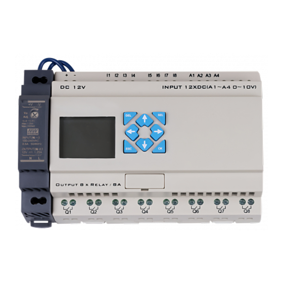
Model LSC-08
The LSC-08 is a standalone load shedding controller designed to work with any single or three phase generator and a
broad range of connected load types controlled by DRY CONTACTS. The controller can be set for 2 different
configurations as follows. Normally open Mode is selected when I2 = 24Vdc this mode is designed to work with
loads that use a normally open state for control purposes like normally closed relays. The Normally Closed Mode is
selected when I2 = 0V This mode is designed to work with normally closed control circuits like low voltage HVAC
control wires and normally open contactors.
Theory Of Operation
Operation: The internal program starts to run on power up. At startup all relays will revert to their active state, NO
Configuration will close and NC Configuration will open. All relays will remain in their active state for the
duration of the Delay Shed period set by DR01. After DR01 times out the program will look at the value of Gen
Full Load DR02 to determine the maximum amps available. A comparator circuit will look at the assigned amperage
rating of DR03 Relay1 and the Gen Actual Cur reading, (this will always be determined by the higher of the 3 CT
inputs). When capacity is available Relay1 will revert to the NORMAL STATE and turn the load on. After the load
is restored the program will pause for the number of seconds set by input setting DR0A Stabilize Time. After the
delay period the program will compare the Gen Actual Cur reading, with Gen Full Load DR02 and the amps
assigned to RELAY2 DR04, if the comparator program determined capacity is available RELAY2 will revert to its
normal state turning on load 2. This sequence is repeated for RELAY 8 ~RELAY 8 . Any time the Gen Actual Cur
reading exceeds 90% of Gen Full Load DR02 All relays will revert to their active state removing all eight of the
loads from the circuit. The program will then repeat the process restoring one load at a time until additional capacity
is no longer available.
Programming Screens
Screens 1 to 5 and 7 to 8 are used to adjust the Amperage and time delays in the load shedding program. Note that
screen 4 "Gen Actual Cur" is not adjustable and is reading the amperage interpreted by the CT input. Also note that
screen 6 & 10 displays the real time state of the output relays on the controller. Screen 7 indicated the NO or NC
Mode of operation.
Screen 3
Screen 1
Screen 2
Screen 4
Screen 6
Screens 5
Screen 7
Screens 8 & 9
Screen 10
Advertisement
Table of Contents

Related Manuals for PSP LSC-08


Summary of Contents for PSP LSC-08
- Page 1 Model LSC-08 The LSC-08 is a standalone load shedding controller designed to work with any single or three phase generator and a broad range of connected load types controlled by DRY CONTACTS. The controller can be set for 2 different configurations as follows.
- Page 2 Programming Instructions Left Arrow Key- The left arrow key is used to scroll thru screens 1 to 10. The screen sequence will be repeated after screen 10. Note: The right arrow key does not scroll in reverse. Entering The Programming Mode- The select key is used to enter the programming mode on any screen.
- Page 3 Programmable Field Descriptions Generator Full Load DR02- Adjust to generators maximum amperage output in whole amps. DelayShed DR01 - Delay period in seconds from the generator start up until the 1st load will be restored. Relay #1 Current DR03- Adjust to the estimated maximum amperage draw in whole amps for load # 1 Relay #2 Current DR04 - Adjust to the estimated maximum amperage draw in whole amps for load #2...
- Page 4 Scroll to select field to adjust Push to save adjustment 120 Volt AC Open Frame Contactor HVAC Control Relay Relay Voltage Voltage 100-200 Amp Latching Relays PSP Producs Inc. - 8535 Phoenix Drive, Manassas, VA 20110 www.pspproducts.com - 800-648-6802 Email Sales@PSPProducts.com...
Need help?
Do you have a question about the LSC-08 and is the answer not in the manual?
Questions and answers