Advertisement
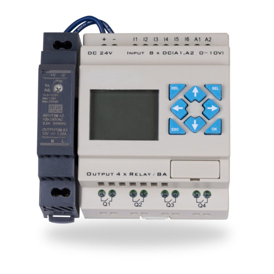
4 Circuit Load Management Controller Wiring
Note: All control voltage inputs are DC voltage and correct polarity must be observed or damage to the
controller may occur.
Closed - Utility Mode
Open - Generator Mode
*See Note
-
+
24 Volt DC
Power Supply
Provided
120 Volt AC
Input
Contactor
Voltage
110/24Vac
* When CT's are attached to generator out puts L1 & L2 directly input I1 is not required. When CT's are connected to main panel or transfer switch out put I1 input is required to bypass load
shedding in utility mode. Contacts not supplied with LSC-04
PSP Producs Inc. - 8535 Phoenix Drive, Manassas, VA 20110
www.pspproducts.com - 800-648-6802 Email Sales@PSPProducts.com
Diagram and Programming Instructions
I1
I2
Closed - Normally Open
Open - Normally Closed
*See Note
I2
I1
Scrolls Between Windows
100-200 Amp Latching Relays
Load Shedding Control
Model LSC-04
Current Transformers
L1
+
HVAC
Relay Voltage
Control Wires
110/24Vac
L2
Important: Observe CT polarity or
damage may occur to controller or CT.
-
-
+
Push to enter field to adjust mode
Scroll to select field to adjust
Push to save adjustment
Open Frame
Relay
Advertisement
Table of Contents

Related Manuals for PSP LSC-04


Summary of Contents for PSP LSC-04
- Page 1 * When CT’s are attached to generator out puts L1 & L2 directly input I1 is not required. When CT’s are connected to main panel or transfer switch out put I1 input is required to bypass load shedding in utility mode. Contacts not supplied with LSC-04 PSP Producs Inc.
- Page 2 Load Shedding Control Model LSC-04 The LSC-04-S is a standalone load shedding controller designed to work with any single phase generator and a broad range of connected load types controlled by DRY CONTACTS. The controller can be set for 2 different configurations as follows.
- Page 3 Programming Instructions Left Arrow Key- The left arrow key is used to scroll thru screens 1 to 7. The screen sequence will be repeated after screen 7. Note: The right arrow key does not scroll in reverse. Entering The Programming Mode- The select key is used to enter the programming mode on any screen.
- Page 4 Programmable Field Descriptions Generator Full Load DR02- Adjust to generators maximum amperage output in whole amps. DelayShed DR01 - Delay period in seconds from the generator start up until the 1st load will be restored. Relay #1 Current DR03- Adjust to the estimated maximum amperage draw in whole amps for load # 1 Relay #2 Current DR04 - Adjust to the estimated maximum amperage draw in whole amps for load #2...
Need help?
Do you have a question about the LSC-04 and is the answer not in the manual?
Questions and answers