Table of Contents
Advertisement
Quick Links
Model:
SH-SmartStat
This thermostat has been designed to provide you with years of trouble free
service. Proper understanding of any product is the key to using it
successfully. By spending only a few minutes reading through this manual,
you will become acquainted with the many features built into this
thermostat. Following the procedures listed within this manual will minimise
the risk of damaging the thermostat or any of the equipment it controls.
Please take special notice of all
information and safety tips.
1. CONTENTS
SPECIFICATIONS .................................. 2
POSITIONING THE THERMOSTAT........ 3
OPENING THE THERMOSTAT.............. 4
TOOLS REQUIRED................................ 5
PREPARATION & WALL MOUNT........... 6
WIRING DIAGRAMS............................... 7
Features.............................................. 8
FLOOR TEMPERATURE SENSOR....... 9
2. SPECIFICATIONS
PHYSICAL DIMENSIONS:
L 125mm X W 90mm X D 34mm
MAX. SWITCHING CAPACITY:
230Vac / 8 Amp (1.8 kW) Resistive.
POWER SUPPLY: 230Vac 50 Hz
TEMPERATURE DISPLAY: Celsius
TIME DISPLAY: 24 hour
TEMPERATURE DIFFERENTIAL
0.5-1.0°C (Fact. = 0.5°C)
3. THERMOSTAT POSITIONING
Proper positioning of the thermostat is very important to
!
ensure accurate room temperature measurement.
Observe the following general rules for best results.
1. The thermostat should be fitted on an inside wall of the room where the
heating is installed, approx. 1.5 m (5 ft.) above the floor.
2. Avoid areas which have unusual heating or cooling conditions, such as
direct sunlight, near a fireplace, stove, door, window or stairway.
3. Be aware of furnishings which may block airflow or alter the temperature
such as: sofas, chairs, bookcases, track lighting, lamps, stereo equipment,
television sets etc.
4. Note that hot water pipes in the wall, a stove, refrigerator or fireplace on
the other side of the wall may also affect the operation and accuracy of
your thermostat.
5. Positioning the thermostat in a damp area will cause corrosion and shorten
the life of the thermostat.
6. Do not install the unit where air circulation is poor (e.g. in a corner, alcove,
or behind a door).
7. All construction work and painting must be completed before installation.
N.B. This thermostat does not require levelling.
To avoid electrical shock and to prevent damage
!
to the floor heating and thermostat, disconnect
the power supply before proceeding with the
installation.
PROGRAMMABLE THERMOSTAT
!
IMPORTANT!
READ THE INSTRUCTIONS
BEFORE INSTALLATION.
!
NOTES
as these contain important
Setting The Clock.................. 11
Programming.......................... 12
MANUAL OPERATION MODE........ 14
Temporary Override............. 15
Comfort Override................. 16
Battery Low Indicator...........17
SET-POINT ADJUSTMENT: 1.0
TEMPERATURE DISPLAY RANGE:
-10 to 45°C
TEMPERATURE CONTROL RANGE:
5 to 32°C
PROGRAMMING PERIODS:
Monday - Friday : 6 periods / Day
Saturday - Sunday : 4 periods / Day
OPTIONAL ACCESSORY:
Floor sensor cable for max. floor
temperature limitation.
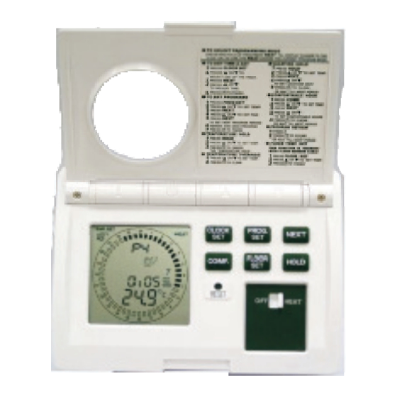
4. OPENING THE THERMOSTAT
!
Be careful not to drop the body or to disturb any electronic parts.
Leave the flap closed and separate the body from the base plate.
Hold on firmly to the baseplate with your other hand by placing your fingers
on both sides of the thermostat. Whilst keeping the release button pressed,
swing the thermostat away from it's base.
To refit the thermostat body to the base plate, hook the body onto the
bottom of the base plate (see photograph). Press both parts together until
the unit snaps shut.
5. TOOLS REQUIRED:
#1 Philips Screw driver (small)
Drill with 4.5 mm (3/16") bit (if using anchors)
Wire strippers or utility knife, masking tape & pen (for labelling wires).
6. PREPARATION AND WALL MOUNT
When mounting the thermostat on a
soft surface, like plasterboard, where
the screws might not hold securely,
you will need to make mounting holes.
Remove the terminal cover.
°C
Hold thermostat base against the wall,
with the electric wires coming through
wherever it is convenient for wiring.
Route the wires above the terminal
strip and attach the base to the wall
with the screws provided.
7. WIRING DIAGRAMS
8A (2A)
Before you connect the wiring you must check your system's wiring
diagram or consult with a professional electrician.
Note that the maximum load should be limited to 8 Amps (1800
Watt @ 230 Vac). For bigger loads, use a slave contactor.
8A (2A)
1
While holding the thermostat
face in the palm of your hand,
press the release button with
your thumb.
Attach wires to terminal screws
using the appropriate wiring
diagram (see 7). When finished,
refit the terminal cover.
NB. If you are unfamiliar with
electrical wiring, contact an
electrician for assistance.
Connect the electric
wiring as shown
in the diagram on the
inside of the base
Thermostat
Live supply
Heater(s)
4
Blue or
Gn+Yw
HEATER
Brown or
Bk+Rd
Using the base as a
guide, mark the screw
locations on the wall.
Drill a 5 mm (3/16")
hole at each of the
screw locations, and
insert plastic anchors.
plate.
5
6
FUSE
L
N
220V - 240V
50-60 Hz
Advertisement
Table of Contents

Related Manuals for Speedheat SH-SmartStat


Summary of Contents for Speedheat SH-SmartStat
- Page 1 Be careful not to drop the body or to disturb any electronic parts. Model: Leave the flap closed and separate the body from the base plate. SH-SmartStat While holding the thermostat face in the palm of your hand, press the release button with your thumb.
- Page 2 2) Mode "7d" which sets individual programmes for each day of the week. 8. FEATURES Once the power is connected the LCD SCREEN will show all symbols for 5 Saves programmes in seconds. Thereafter, the LCD SCREEN will display "5:2d" (default). You memory and returns to normal display can now press the "NEXT"...
- Page 3 12. PROGRAMMING Ensure that the OFF/HEAT switch is in the HEAT position, When either of these temperatures are reached the otherwise the following operations will not work! thermostat will switch the heating system off. TO CHANGE a programme memory, press PROG.
- Page 4 45 seconds to install new programme period. At the start of the next programme batteries without losing the settings!. period, the override will be cancelled and the thermostat will return to programme mode. FOR MORE INFORMATION VISIT OUR WEB SITE ON : www.speedheat.co.za...
Need help?
Do you have a question about the SH-SmartStat and is the answer not in the manual?
Questions and answers