Advertisement
Quick Links
Advertisement

Related Manuals for Lush Projects LushOne Inca

Summary of Contents for Lush Projects LushOne Inca
- Page 1 LushOne Inca Synth Module Introduction, Joystick, Signal Processing Joystick...
- Page 2 • Noise source – Random voltage source and percussive sound • Sample and Hold – Capture and hold voltage levels from clock • Low Frequency Oscillator (LFO) • Analogue thumbstick with switch • 3.5mm mono Break-in/Breakout 2 LushOne 301 – LushOne Inca...
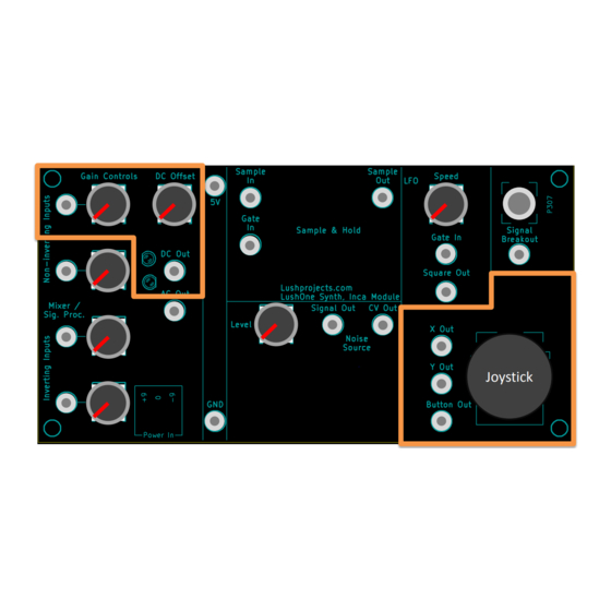
- Page 3 LushOne Inca layout and controls Break-In/ Mixer/Signal Processor Sample and Hold Breakout Joystick Joystick Noise Source = 2mm banana plug patch connector 3 LushOne 301 – LushOne Inca...
- Page 4 In this teaching module • Using the joystick • Using one input of the mixer as a signal processor to manipulate a control voltage (CV) Joystick 4 LushOne 301 – LushOne Inca...
- Page 5 • Button Out goes from 0V (joystick not pressed) to +5V (joystick pressed) • Connect through the Mixer/Signal Processor to change range of polarity of outputs • The joystick makes me smile 5 LushOne 301 – LushOne Inca...
- Page 6 CV In “Gate In” can be connected to one of: 1) 5V for continuous operation 2) Button Out for control by Joystick LushOne Base Module 3) LFO Square Out for regular beats Inca Module 6 LushOne 301 – LushOne Inca...
- Page 7 • Try different wave shapes • Try connecting the “Gate In” to other sources: – “Button Out” on the joystick – press joystick for sound – “Square Out” on Inca LFO for repeating bursts Joystick Twiddle joystick 7 LushOne 301 – LushOne Inca...
- Page 8 • Using the Mixer/Signal Processor as a signal processor you can manipulate control voltages – Control the gain – Add or subtract a voltage offset Or any combination! – Invert the polarity of a signal 8 LushOne 301 – LushOne Inca...
- Page 9 – Allows control voltages between 0V and 5V – AC output will go negative • Use the two LEDs to monitor the output voltage (see next slide) 9 LushOne 301 – LushOne Inca...
- Page 10 Fast AC signals will cause steady lights DC Out = -5V again (due to persistence of vision hiding the fast flicker) • With practice you will learn to infer the signal behaviour from the pattern of the lights 10 LushOne 301 – LushOne Inca...
- Page 11 Gain ≈ 1 the CV – For non-inverting inputs: = (Gain x V + Offset – For inverting inputs: = - (Gain x V + Offset Gain = 0 Gain = 3 Add -5V Add +5V 11 LushOne 301 – LushOne Inca...
- Page 12 Keep a short eye on the LEDs – in particular watch for the negative LED lighting up! • Some inputs (eg CV in to the filter) are not too sensitive about the voltage in and can be more freely used. 12 LushOne 301 – LushOne Inca...
- Page 13 • Add patch lead to OSC1 CV In • Follow procedure on previous slide to progressively adjust the Signal Processor Controls Joystick to get a range of effects you like while keeping within the allowed voltages Twiddle joystick 13 LushOne 301 – LushOne Inca...
- Page 14 • Use the signal processor to change responses to control voltages • Don’t forget if you also have a contour you can invent patches involving all three modules • Next time: – Using the Mixer to combine signals – Interconnecting external signals 14 LushOne 301 – LushOne Inca...
Need help?
Do you have a question about the LushOne Inca and is the answer not in the manual?
Questions and answers