Table of Contents
Advertisement
Quick Links
Advertisement
Table of Contents

Related Manuals for GSi Protek 1000 Series

Summary of Contents for GSi Protek 1000 Series
- Page 1 1000MENUAL.indd 1 2009-04-06 9:06:39...
- Page 2 1000MENUAL.indd 2 2009-04-06 9:06:40...
- Page 3 USER’S MANUAL 1000MENUAL.indd 3 2009-04-06 9:06:44...
- Page 4 USER’S MANUAL 1006 / 1020 / 1050 / 1160 / 1260 1000MENUAL.indd 1 2009-04-06 9:06:45...
-
Page 5: Table Of Contents
Content Safety Notice …………………………………………………..3 Digital Scope Meter……………………………………………5 CHAPTER 1: Getting Started…………………………………6 General Check………………………………………..6 User’s Interface……………………………………...…6 Input Connections…………………………………..11 Function Check……………………………………….12 To compensate probes……………………………..13 To display a signal automatically…………………..15 Using the Scope Meter……………………………..15 CHAPTER 2: Operating Scope……………………………..18 Set Vertical System…………………………………...18 Set Horizontal System………………………………..29 Set Trigger System…………………………………...33 Save / Recall Waveforms and Setups……………...37 Utility Function………………………………………...41... -
Page 6: Safety Notice
General Safety Notice 1. Safety Terms and Symbols Terms in this manual: These terms may appear in this manual: WARNING: Warning statements identify conditions or practices that could result in injury or loss of life. CAUTION: Caution statements identify conditions or practices that could result in damage to this product or other property. - Page 7 ■ Connect and Disconnect Properly. Do not connect or disconnect probes or test leads while they are connected to a voltage source. ■ Connect and Disconnect Properly. Connect the probe output to the measurement device before connecting the probe to the circuit under test. Disconnect the probe input and the probe reference lead from the circuit under test before disconnecting the probe from the measurement device.
-
Page 8: Digital Scope Meter
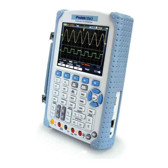
Digital Scope Meters Protek1000 Series digital scope meters offer exceptional waveform viewing and measurements in a compact, lightweight package. Protek1000 series is ideal for production test, field service, research, design, education and training involving applications of analog circuit tests and troubleshooting. Product features: ■... -
Page 9: Chapter 1: Getting Started
Accessories supplied with the instrument are listed in “Accessories” in this guide. If the contents are incomplete or damaged please notify our distributor at your local area or the overseas sales dept. of GSI. ■ Check the instrument: In case there is any mechanical damage or defect, or the instrument does not operate properly or fails performance tests, please notify our distributor at your local area or the overseas sales dept. - Page 10 Figure 1-1 Protek1000 Series H/H Scope Meter Front Panel 1000MENUAL.indd 7 2009-04-06 9:06:46...
- Page 11 Figure 1-2 Front Panel Description Description 1. LCD Display. 2. F1~F5: Sets or switch options for the menu. 3. Arrow Keys 4. Hori: Shows Hori menu 1000MENUAL.indd 8 2009-04-06 9:06:49...
- Page 12 5. TRIG: Shows TRIG menu 6. Level: Adjust the trigger level. 7. RUN/STOP: key for running or stopping the operation. 8. AUTO: Be used for auto setting under the oscilloscope operation mode 9. TIME/DIV: Decrease or Increase the time base. 10.
- Page 13 Description 1. Shows running status. 2. Shows delay time 3. Shows location of the current waveform in the memory. 4. Shows the trigger position in the memory. 5. Shows the trigger mode. 6. Shows the trigger source. 7. Shows the trigger level. 8.
-
Page 14: Input Connections
Input Connections See the following Figure 4: Figure 1-4 Input Connections Description: 1) The power adapter is supplied for AC power supply and battery recharging. 2) Multi-meter test lead. 3) Multi-meter input jacks, including three circular banana jacks and tow square jacks. The three circular jacks are used for voltage, current and resistance inputs, while the two square jacks are used for capacitance inputs. -
Page 15: Function Check
Function Check Perform this quick functional check to verify that your scope meter is operating correctly. 1. Turn on the instrument. Use the power cords designed for your scope meter only. Use a power source that delivers 100 to 240 VACRMS, 50Hz. Turn on the scope meter. WARNNING: To avoid electric shock, be sure the scope meter is properly grounded. -
Page 16: To Compensate Probes
To compensate probes Perform this adjustment to match the characteristics of the probe and the channel input. This should be performed whenever attaching a probe to any input channel the first time. CH1→Probe→10X 1. From CH1 menu, set the Probe attenuation to 10X (press Set the switch to 10X on the probe and connect it to CH1 of the scope meter. - Page 17 Under Compensated 3. If necessary, use a non-metallic tool to adjust the trimmer capacitor of the probe for the flattest square wave being displayed on the oscilloscope. 4. Repeat if necessary. WARNNING: To avoid electric shock while using the probe, be sure the perfection of the insulated cable, and do not touch the metallic portions of the probe head while it is connected with a voltage source.
-
Page 18: To Display A Signal Automatically
To display a signal automatically Protek1000 Series has an Auto feature that automatically sets up the scope meter to best display the input signal. Using Auto requires signals with a frequency greater than or equal to 50 Hz and a duty cycle greater than 1%. AUTO Press the button, the scope meter turns on and scales all channels that have... - Page 19 Figure 1-6 Menu Operation The following example shows how to use the tools menus to select a function, as shown in the following figure. Figure 1-7 The Menu 1000MENUAL.indd 16 2009-04-06 9:06:57...
- Page 20 MENU ON/OFF 1. Press the key to display the Function Menu on the bottom of the MENU ON/OFF screen and the corresponding optional settings on the bottom. Press again to hide the Function Menu. 2. Choose one key from and press it to change function setting. To set up the vertical system 1.
-
Page 21: Chapter 2: Operating Scope
CHAPTER 2: Operating Scope The end-user should know how to determine the system setup from the status bar of a Protek1000 series scope meter. This chapter will show the detailed function of the test tool. ■ Set Vertical System ■ Set Horizontal System ■... - Page 22 The following table describes the channel menu: Menu Setting Description Turn on Channel Enable Turn off Channel The dc component in the input signal is blocked Coupling The ac and dc components of the input signal are allowed Disconnect the input signal. Select one according to the probe attenuation factor to ensure correct vertical scale reading Probe...
- Page 23 2. Set Channel Coupling With CH1 taken for example, input a sine wave signal containing a DC offset. CH1→Coupling→AC Press to set “AC” coupling. It will pass AC component blocks the DC component of the input signal. The waveform is displayed as Figure 2-3 Figure 2-3 Waveform Display CH1→Coupling→DC...
- Page 24 The waveform is displayed as Figure 2-4: Figure 2-4 Waveform Display CH1→Coupling→GND Press , to set “GND” coupling, it disconnects the input signal. The screen displays as Figure 2-5: 1000MENUAL.indd 21 2009-04-06 9:07:01...
- Page 25 Figure 2-5 Waveform Display 3. Set Probe Attenuation The scope meter allows adjusting the probe attenuation scale factor correspondingly in the channel operation menu in order to comply with the probe attenuation scale. The attenuation factor changes the vertical scaling of the scope meter so that the measurement results reflect the actual voltage levels at the probe tip.
- Page 26 Figure 2-7 Invert off Figure 2-8 Invert on 1000MENUAL.indd 23 2009-04-06 9:07:04...
- Page 27 5. Set Band-Width Limit With CH1 taken for example, input a signal containing high frequency component. CH1→F5→F3→OFF Press , to set up bandwidth limit to “OFF” status. The oscilloscope is set to full bandwidth and passing the high frequency component in the signal.
- Page 28 Figure 2-10 BW limit On 6. Math Setting The mathematic functions include “add”, “subtract”, “multiply”, “division”, and “FFT” for Channel 1 and Channel 2. The mathematic result can be measured by the grid and the cursor. The Math menu Figure 2-11 The Math menu The Math menu setting table Menu...
- Page 29 Source A Define CH1 or CH2 as source A. Define CH1 or CH2 as source A. Source B Invert the MATH waveform. Invert Waveform display normal. 7. FFT The FFT (Fast Fourier Transform) process converts a time-domain signal into its frequency components mathematically.
- Page 30 2) To reduce random noise and aliases components in repetitive or single-shot events, set the oscilloscope acquisition mode to average. 3) To display FFT waveforms with a large dynamic range, use the “dBVrms” scale. The “dBVrms” scale displays component magnitudes using a log scale. FFT Window Protek1000 series scope meter provides four FFT windows.
- Page 31 REF menu table when using internal memory Menu Setting Description Select channel1 as REF channel. Source Select channel2 as REF channel. Internal Select memory location in scope. Location External Select memory location out scope. Save REF waveform. Save Go to import/export menu. Load REF menu table when using external memory Menu...
-
Page 32: Set Horizontal System
Display a Reference Waveform Figure 2-15 Reference display 1) Press M/R button to show the reference waveform menu. 2) Press F2 to select the reference channel: CH1, CH2. 3) Press F5 to load an internal REF file. 4) Press F1 button to turn on REF. NOTE: The Reference function is not available in X-Y mode. - Page 33 The Horizontal Menu: Figure 2-16 The Horizontal Buttons The Horizontal Menu Table Menu Setting Description Y – T Show the relative relation between vertical voltage and horizontal time. X – Y Show CH1 value at X axis; CH2 value at Y axis. Time base Roll In Roll Mode, the waveform display updates...
- Page 34 Figure 2-19 The horizontal/Time base marks Marks Indicator 1. The current waveform window’s position in the memory. 2. The trigger position in the memory. 3. The trigger’s horizontal offset according to the center of the window. 4. The horizontal time base (main time base). 5.
- Page 35 Figure 2-20 X-Y display format The following modes or functions will not work in X-Y format. ■ Automatic Measurements ■ Cursor Measurements ■ REF and MATH Operations ■ Horizontal Position ■ Trigger Controls 1000MENUAL.indd 32 2009-04-06 9:07:14...
-
Page 36: Set Trigger System
Set Trigger System The trigger determines when the scope meter starts to acquire data and display a waveform. When a trigger is set up properly, it can convert unstable displays or blank screens into meaningful waveforms. When the scope meter starts to acquire a waveform, it collects enough data so that it can draw the waveform to the left of the trigger point. - Page 37 Auto Acquire waveform even no trigger occurred. Sweep Normal Acquire waveform when trigger occurred. Singl When trigger occurs, acquire one waveform then stop. Reject high frequency signals. Reject Pulse Trigger Setting Pulse trigger occurs according to the width of pulse. The abnormal signals can be detected through setting up the pulse width condition.
- Page 38 Auto Acquire waveform even no trigger occurred. Sweep Normal Acquire waveform when trigger occurred. Single When trigger occurs, acquire one waveform and then stop. Reject high frequency signals. Reject Note : The Pulse width adjust range is 20ns ~ 10s. When the condition is met, it will trigger and acquire the waveform.
- Page 39 +more +Pulse width more than +Less +Pulse width less than +Equal +Pulse width equal to When -more -Pulse width more than -Less -Pulse width less than -Equal -Pulse width equal toTo select pulse condition. The Alternative menu (Trigger Type: Pulse Page 2/2) Menu Setting Description...
-
Page 40: Save / Recall Waveforms And Setups
Save / Recall Waveforms and Setups Save/Recall Press the button, the interface menu for settings shows as follows. The Save/Recall Menu Table Menu Setting Description Wave Store or recall waveform. Setup Store or recall instrument setups. Type Bitmap Create or delete bit map files. Create or delete CSV files. - Page 41 Bitmap The Bitmap menu Figure 2-27 The Bitmap menu The Bitmap menu table Menu Setting Description External Go to menu for external memoryoperation The CSV menu Figure 2-28 The CSV menu The CSV menu table Menu Setting Description External Go to menu for external memoryoperation Factory The Factory menu Figure 2-29...
- Page 42 Recall waveform files and setup files from the Save internal memory location. Save waveform files and setup files to the Load internal memory location. External Memory SAVE/RECALL → External Press to go to the following menu. Menu Setting Description To create new file New File Delete file Delete File...
- Page 43 Factory The scope meter has default settings and can be recalled at anytime by Memory location Specify the memory location to save/recall the waveforms and setups. Load Recall saved waveforms, setups and default settings. Save Save waveforms and setups. NOTE: 1.
-
Page 44: Utility Function
Utility Function Utility Utility Press the button to show the menu of the settings in the system. The Utility menu (Page 1/3) Figure 2-31 The Utility menu The Utility menu (Page 2/3) Figure 2-32 The Utility menu The Utility menu (Page 3/3) Figure 2-33 The Utility menu The Utility menu (Page 1/3) - Page 45 Record Go to Record menu Language English EnglishChinese Select languages. Chiness (More languages may be added in later firmware versions.) The Utility menu (3/3) Menu Setting Description Infinite Shut 5MIN Set the shut down time Down 30MIN Bright Value Set the shut down time Calibrate the scope meter Calibrate Calibrate...
- Page 46 Figure 2-34 The Calibration Screen NOTE: 30-minutes The scope meter must have been working or warm-up at least before running calibration to get best accuracy. The scope meter will calibrate parameter of vertical system (CH1, CH2). Pass/Fail The Pass/Fail function monitors changes of signals and output pass or fail signals by comparing the input signal is within the pre-defined mask.
- Page 47 The Pass/Fail menu table (Page 1/2) Menu Setting Description Enable Turn on Pass/Fail test. Turn off Pass/Fail test. Source Select Pass/Fail test on CH1. Select Pass/Fail test on CH2. Output Fail Output when Fail condition detected. Pass Output when Pass condition detected. Operate Stop Pass/Fail test stopped, press to run.
- Page 48 The Mask setting menu table (Page 1/2) Menu Setting Description Set horizontal clearance to the waveform (0.04div- Vertical 4.00div). Set vertical clearance to the waveform(0.04div-4.00div). Horizontal Create a test mask according to the above clearance. Create Internal Store created test mask into internal/External memory. Location External The Mask setting menu table (Page 2/2) When the save as internal memory...
- Page 49 The Recorder menu (Page 2/2) Figure 2-40 The Recorder menu The Record menu table (Page 1/2) Menu Setting Description Record Select record mode. Play back Select play back mode. Mode Storage Select storage mode. Turn off all recorder function. Select record source channel. Source End Frame <1-1000>...
- Page 50 The Record menu table (Page 1/2) Menu Setting Description Operate Start Play stopped, press to Start playback. Stop Press to stop playing. Repeat Set repeat play mode or not. Interval <1.00ms-20s> Set interval time to play back. The Record menu table (Page 2/2) Menu Setting Description...
- Page 51 The Storage menu when the save to Internal memory (Page 2/2) Menu Setting Description Save Save recorded waveform to internal memory location. Load Recall recorded waveform from internal memory location. Imp/Exp Go to import/export menu (Same asREF import/export menu). The Storage menu when the save as external memory (Page 2/2) Menu Setting Description...
-
Page 52: Signal Measurement
Signal Measurement MEAS Press the button to display the menu of the automatic measurements settings. The measure menu Figure 2-45 The Measure menu The oscilloscopes provide 18 auto measurements: Vpp, Vmax, Vmin, Vtop, Vbase,Vamp, Vavg, Vrms, Overshoot, Preshoot, Freq, Period, Rise Time, Fall Time, +Width, -Width, +Duty, -Duty (10 voltage and 8 timing measurements). - Page 53 The Root Mean Square voltage over the entire waveform Positive Overshoot = (Max - Top)/Amp x 100 % Preshoot Measured over the entire waveform Negative Overshoot = (Base - Min)/Amp x 100 % Overshoot -Measured over the entire waveform The Time Measurement menu Menu Description Time to take for the first signal cycle to complete in the waveform...
-
Page 54: Cursor Measurement
Cursor Measurement The screen displays two parallel cursors. Move the cursors to make custom voltage or time measurements of the signal. The values are displayed on the boxes below the menu. Before using cursors, make sure to set the Signal Source as the channel for measuring. - Page 55 5. Move the cursors to adjust the increment between the cursors. The values will be automatically displayed on the right upper corner of screen when the cursor function menu is hidden or displaying other menus. 1000MENUAL.indd 52 2009-04-06 9:07:19...
-
Page 56: Chapter 3: Multimeter
CHAPTER 3: Multimeter About this chapter This chapter provides an introduction to the multimeter functions of Protek1000 Series. The introduction gives guides to show how to use the menus and perform basic measurements. Connecting the Meter Use the 4-mm safety banana jack inputs for the Meter functions: COM,V/Ω, m A A . Multimeter Operation Window Figure 3-1: Multimeter operation window Description... - Page 57 4) The reading value of measurement. 5) The bar graph indictor. 6) DC or AC Measurement mode control. 7) Absolute /relative magnitude measuring control: The sign “||” expresses the absolute magnitude measuring control and “ ” represents the relative magnitude measuring control.
- Page 58 Making a Diode Measurement To make a measurement on the diode, do the following: 1) Press the diode key and a diode symbol appears at the top of the screen. 2) Insert the black lead into the COM banana jack input and the red lead into the V/ Ω...
- Page 59 Then, the screen will look like the following figure 3-4. Figure 3-4: On-off Measurement Making a Capacitance Measurement To measure a capacitance, do the following: 1) Press the C key and a capacitor symbol appears on the top of the screen. 2) Insert the black lead into the COM banana jack input and the red lead into the V/ Ω...
- Page 60 Then, the screen will look like the following figure 3-5. Figure 3-5: Capacitance Measurement Making a DC Voltage Measurement To measure a DC voltage, do the following: 1. Press the V key and DC appears at the top of the screen. 2.
- Page 61 Then, the screen will look like the following figure 3-6. Figure 3-6: DC voltage Measurement Making a AC Voltage Measurement To measure the AC voltage, do the following: 1) Press the V key and DC appears at the screen. 2) Press the F1 key and AC appears at the screen. 3) Insert the black lead into the COM banana jack input and the red lead into the V/ Ω...
- Page 62 Then, the screen will look like the following figure 3-7. Figure 3-7: AC voltage Measurement Making a DC Current Measurement To measure a DC current, which is less than 600 mA, do the following: 1) Press the A key and DC appears at the screen. The unit on the main reading screen is mA.
- Page 63 Then, the screen will look like the following figure 3-8. Figure 3-8: DC current Measurement for 600 mA To measure a DC current, which is larger than 600 mA, do the following: 1) Press the A key and DC appears on the screen. The unit on the main reading screen is mA..
- Page 64 Then, the screen will look like the following figure 3-9. Figure 3-9: DC Current Measurement for 10A Making an AC Current Measurement To measure an AC current, which is less than 600 mA, do the following: 1) Press the A key and DC appears on the screen. The unit on the main reading screen is mA,and mA will display on the bottom of the screen, press F2 to switch the measurement between mA and 10A.
- Page 65 Then, the screen will look like the following figure 3-10. Figure 3-10: AC Current Measurement for 600 mA To measure an AC current, which is larger than 600 mA, do the following: 1) Press the A key and DC appears on the screen. The unit on the main reading screen is mA.
- Page 66 Then, the screen will look like the following figure 3-11. Figure 3-11: AC Current Measurement for 10A Taking a Relative Measurement A currently measured result relative to the defined reference value is displayed in a relative measurement. The following example shows how to take a relative measurement. At first, it is required to acquire a reference value.
- Page 67 Then, the screen will look like the following figure 3-12. Figure 3-12: Relative Measurement Selecting Automatic/Manual Range Adjustment The defaulted range mode of the instrument is automatic range. Suppose you are using the DC voltage mode, to switch to the manual range, perform the following steps: 1) Press F3 key and MANUAL is displayed on the bottom of the screen to enter the manual range mode.
-
Page 68: Chapter 4: Troubleshooting
Then, the screen will look like the following figure 3-13. Figure 3-13: Automatic/Manual Range Adjustment Attention : capacitance measurement without manual range mode. CHAPTER 4: Troubleshooting 1. The scope meter cannot be turned on. 1) Check the power cable connection. 2) Ensure the power switch is turned on. -
Page 69: Chapter 5: Specifications
Persistence is set ON, the waveform refreshes slowly. It is normal in these settings. CHAPTER 5: Specifications Vertical Channels Protek1006: 60MHz Protek1020: 200MHz Bandwidth Protek1050: 500MHz Protek1160: 600MHz Protek1260: 600MHz Protek1006: 5.8ns Protek1020: 1.7ns Protek1050: 0.7ns Rise Time Protek1160: 0.58ns Protek1260: 0.58ns Resistance: 1M;Capacitance: 15pF Input Impedance... - Page 70 Protek1006: 5ns/div ~ 1000s/div Protek1020: 2ns/div ~ 1000s/div Time Base Range Protek1050: 1ns/div ~ 1000s/div Protek1160: 1ns/div ~ 1000s/div Protek1260: 1ns/div ~ 1000s/div Time Base ±50ppm Precision Trigger Source CH1, CH2 Protek1006: Edge, Pulse Width, Alternative Mode Protek1020, 1050, 1160, 1260: Edge, Pulse Width, Alternative, Video.
- Page 71 Maximum Input AC: 10A DC: 10A Current Input Impedance DISPLAY TFT LCD Type 5.7 Inch width LED Backlight Display Display 240 (Vertical) X 320 (Horizontal) Dots Resolution INTERFACE USB host/Device 2.0 Full Speed Supported Optional RS232, LAN POWER SOURCE AC 100V ~ 240V, 50Hz ~ 60Hz; Line Voltage DC Input: 8.5 Range...
-
Page 72: Chapter 6: Appendix
To get repair service or obtain a copy of the whole warranty statement, please contact with your nearest GSI sales and service office. does not provide any other warranty items except the one being provided by this summary and the warranty statement. The warranty items include but not being subjected to the hinted guarantee items related to tradable characteristic and any particular purpose. - Page 73 2) Use a soft cloth dampened with water to clean the instrument. NOTICE: To avoid damage to the surface of the instrument or probes, do not use any abrasive or chemical cleaning agents. Storage of Scope meter If the test tool is to be stored for a long time, it is required to charge the lithium battery before storage.
Need help?
Do you have a question about the Protek 1000 Series and is the answer not in the manual?
Questions and answers