
Related Manuals for Velleman DVM895


Summary of Contents for Velleman DVM895
- Page 1 DVM895 CAT III 600 V / CAT IV 300 V USER MANUAL HANDLEIDING MODE D'EMPLOI MANUAL DEL USUARIO BEDIENUNGSANLEITUNG INSTRUKCJA OBSŁUGI MANUAL DO UTILIZADOR...
- Page 2 DVM895 V. 01 – 28/11/2017 ©Velleman nv...
- Page 3 Respect the local environmental rules. If in doubt, contact your local waste disposal authorities. Thank you for choosing Velleman! Please read the manual thoroughly before bringing this device into service. If the device was damaged in transit, do not install or use it and contact your dealer.
- Page 4 DVM895 Fuse Capacitor Diode Continuity 3. General Guidelines Refer to the Velleman ® Service and Quality Warranty on the last pages of this manual. This symbol indicates: Read instructions Not reading the instructions and manual can lead to damage, injury or death.
- Page 5 DVM895 Keep the device away from children and unauthorised users. Risk of electric shock during operation. Be very careful when measuring live circuits. There are no user-serviceable parts inside the device. Refer to an authorized dealer for service and/or spare parts.
- Page 6 DVM895 Never use the meter with CAT III installations when measuring voltages that might exceed the safety margin of 600 V above earth ground. Never use the meter with CAT IV installations when measuring voltages that might exceed the safety margin of 300 V above earth ground.
- Page 7 DVM895 The existing categories according EN 61010-1 are: A CAT I-rated meter is suitable for measurements on protected electronic circuits that are not directly connected to mains power, e.g. electronics circuits, control signals… A CAT II-rated meter is suitable for measurements in CAT I-...
- Page 8 DVM895 Pollution Only nonconductive pollution occurs. Occasionally, temporary degree 2 conductivity caused by condensation is to be expected.(home and office environments fall under this category) Pollution Conductive pollution occurs, or dry nonconductive pollution degree 3 occurs that becomes conductive due to condensation that is to be expected.
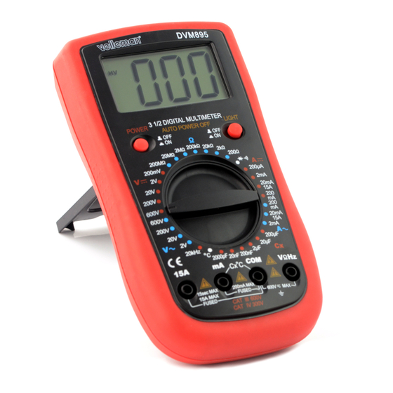
- Page 9 DVM895 backlight ................yes auto power-off ..............yes dimensions ........... 190 x 100 x 40 mm weight (with battery) ............300 g storage environment temperature ..........-20 °C to 60 °C humidity ............< 90 % RH test lead probe ..CAT III 1000 V/ CAT IV 600 V, 15 A; L = 75 cm IP rating ................
- Page 10 DVM895 9.3 DC CURRENT Do not measure circuits that may contain voltages > 600 VDC or > 600 VAC range resolution accuracy 200 µA 0.1 µA 2 mA 1 µA ± (1.2 % rdg + 2 digits) 20 mA 10 µA 200 mA 100 µA...
- Page 11 DVM895 20 MΩ 10 kΩ ± (1.5 % rdg + 3 digits) 200 MΩ 100 kΩ ± (5.0 % rdg + 5 digits) Overload protection: 600 V DC or AC rms 9.6 CAPACITANCE Do not conduct capacitance measurements on live...
- Page 12 DVM895 9.9 TEMPERATURE range accuracy resolution -50 to 150 °C ± (3 °C + 1 digit) °C 1 °C 150 to 800 °C ± (3 % + 1 digit) NiCr-NiSi sensor Overload protection: F0.5 A/600 V fuse 10. Operation 10.1 DC VOLTAGE MEASUREMENT Do not measure circuits that may contain voltages >...
- Page 13 DVM895 Connect the test leads to the source being measured. Read the voltage value and the polarity of the red test lead on the LCD display. Notes See DC Voltage Measurement 10.3 DC CURRENT MEASUREMENT Do not measure circuits that may contain voltages > 600 VDC or >...
- Page 14 DVM895 Connect the red test lead to the “mA” jack and the black test lead to the “COM” jack (switch the red lead to the “15A” jack for measurements between 200 mA and 15 A). Open the circuit in which the current is to be measured and connect the test leads to the circuit IN SERIES.
- Page 15 DVM895 10.7 DIODE AND CONTINUITY TEST Do not conduct diode or continuity measurements on live circuits. Make sure all capacitors in the circuit are depleted. Set the rotary switch in the “ ” (diode) or “ ” (continuity) position. Connect the red test lead to “VHz” jack and the black one to the “COM”...
- Page 16 The information in this manual is subject to change without prior notice. © COPYRIGHT NOTICE The copyright to this manual is owned by Velleman nv. All worldwide rights reserved. No part of this manual may be copied, reproduced, translated or reduced to any electronic medium or otherwise without the prior written consent of the copyright holder.
- Page 17 DVM895 HANDLEIDING DIGITALE MULTIMETER 1999 COUNTS 1. Inleiding Aan alle ingezetenen van de Europese Unie Belangrijke milieu-informatie betreffende dit product Dit symbool op het toestel of de verpakking geeft aan dat, als het na zijn levenscyclus wordt weggeworpen, dit toestel schade kan toebrengen aan het milieu.
- Page 18 Aarding Zekering Condensator Diode Continuïteit 3. Algemene richtlijnen Raadpleeg de Velleman ® service- en kwaliteitsgarantie achteraan deze handleiding. Dit symbool betekent: Instructies lezen Het niet lezen van deze instructies en de handleiding kan leiden tot beschadiging, letsel of de dood.
- Page 19 DVM895 Toestel met vervuilingsgraad 2. Enkel geschikt voor gebruik binnenshuis! Bescherm het toestel tegen regen, vochtigheid en opspattende vloeistoffen. Niet geschikt voor industrieel gebruik. Zie §8 Vervuilingsgraad. Houd dit toestel uit de buurt van kinderen en onbevoegden. Elektrocutiegevaar tijdens het gebruik van deze multimeter.
- Page 20 DVM895 5. Tijdens het gebruik Elektrocutiegevaar tijdens het gebruik van deze multimeter. Wees voorzichtig tijdens het meten van een circuit onder spanning. Gebruik het toestel alleen zoals aangegeven door de fabrikant, anders kan de bescherming waarmee het toestel is beschadigd raken.
- Page 21 DVM895 “VHz”-bus Sluit het rode (+) meetsnoer aan op deze bus om spanning, weerstand en frequentie te meten. 7. Overspannings-/installatiecategorie Multimeters worden opgedeeld volgens het risico op en de ernst van spanningspieken die kunnen optreden op het meetpunt. Spanningspieken zijn kortstondige uitbarstingen van energie die geïnduceerd worden in een systeem door bv.
- Page 22 DVM895 verschillende types vervuiling die in deze omgeving kunnen voorkomen. Deze bescherming hangt hoofdzakelijk af van de isolatie en de eigenschappen van de behuizing. De opgegeven waarde van vervuilingsgraad geeft aan in welke omgeving dit toestel kan gebruikt worden. Vervuilingsgraad Omgeving zonder, of met enkel droge, niet-geleidende vervuiling.
- Page 23 DVM895 display-afmetingen ........... 62 x 36 mm bereikinstelling .............. manueel buiten meetbereik ..............ja continuïteitszoemer ..............ja diodetest ................ja batterij-laag-indicatie .............. ja dataholdfunctie ..............ja achtergrondverlichting............. ja automatische uitschakeling ............ja afmetingen ........... 190 x 100 x 40 mm gewicht (met batterij) ............
- Page 24 DVM895 9.3 GELIJKSTROOM Voer geen metingen uit in circuits met spanningen > 600 VDC of > 600 VAC bereik resolutie nauwkeurigheid 200 µA 0.1 µA 2 mA 1 µA ± (1.2 % v.d. uitlezing + 2 digits) 20 mA 10 µA 200 mA 100 µA...
- Page 25 DVM895 20 MΩ 10 kΩ ± (1.5 % v.d. uitlezing + 3 digits) 200 MΩ 100 kΩ ± (5.0 % v.d. uitlezing + 5 digits) Beveiliging tegen overbelasting: 600 V DC of AC rms 9.6 CAPACITEIT Voer geen capaciteitsmetingen uit in circuits waarop...
- Page 26 DVM895 9.9 TEMPERATUUR bereik nauwkeurigheid resolutie tot 150 °C ± (3 °C + 1 digit) -50 °C 1 °C 150 tot 800 °C ± (3 % + 1 digit) NiCr-NiSi-sensor Beveiliging tegen overbelasting: zekering (F0.5 A/600 V) 10. Gebruik 10.1 GELIJKSPANNINGSMETINGEN (DC) Voer geen metingen uit in circuits met spanningen >...
- Page 27 DVM895 Sluit het rode meetsnoer aan op de "VHz"-bus en het zwarte meetsnoer op de “COM”-bus. Sluit de meetsnoeren aan op de meetbron. De meetwaarde wordt samen met de polariteit van de rode meetsnoer op het LCD-display weergegeven. Opmerkingen ...
- Page 28 DVM895 Zet de draaischakelaar op “ ”. Sluit het rode meetsnoer aan op de "mA"-bus en het zwarte meetsnoer op de “COM”-bus. Sluit het rode meetsnoer aan op de "15A"-bus voor metingen tussen 200 mA en 15 A. Sluit de meetsnoeren IN REEKS aan op het circuit waarvan u de belasting wilt meten.
- Page 29 DVM895 10.7 DIODE EN CONTINUÏTEITSTEST Voer geen diode- of continuïteitsmetingen uit in circuits waarop spanning aanwezig is. Zorg ervoor condensatoren in het circuit volledig ontladen zijn. Zet de draaischakelaar op " " (diode) of " " (continuïteit). Sluit het rode meetsnoer aan op de “VHz”-bus en het zwarte meetsnoer op de “COM”-bus.
- Page 30 (Tip: Vermindert de lichtsterkte van de achtergrondverlichting/LCD-display, dan is de batterij bijna leeg.) Gebruik dit toestel enkel met originele accessoires. Velleman nv is niet aansprakelijk voor schade of kwetsuren bij (verkeerd) gebruik van dit toestel. Voor meer informatie over dit product en de laatste versie van deze handleiding, zie www.velleman.eu.
- Page 31 DVM895 MODE D'EMPLOI MULTIMÈTRE NUMÉRIQUE 1999 POINTS 1. Introduction Aux résidents de l'Union européenne Informations environnementales importantes concernant ce produit Ce symbole sur l'appareil ou l'emballage indique que l’élimination d’un appareil en fin de vie peut polluer l'environnement. Ne pas jeter un appareil électrique ou électronique (et des piles éventuelles) parmi les déchets...
- Page 32 Fusible Condensateur Diode Continuité 3. Directives générales Se référer à la garantie de service et de qualité Velleman ® en fin de ce mode d'emploi. Ce symbole indique : Lire les instructions Ne pas lire les instructions ou le mode d'emploi peut causer des endommagements ou blessures, ou entraîner la mort.
- Page 33 DVM895 Cette appareil correspond au degré de pollution 2. Uniquement pour l'usage à l’intérieur. Protéger l'appareil de la pluie, de l'humidité, d'éclaboussures et des projections d’eau. Ne convient pas à un usage industriel. Se référer à §8 Degré de pollution.
- Page 34 DVM895 Utiliser l’appareil uniquement pour les applications décrites par le fabricant pour éviter d’endommager les systèmes de protection. Ne jamais dépasser les valeurs de limite indiquées. Ne jamais dépasser les valeurs de limite indiquées dans les spécifications de chaque plage de mesure.
- Page 35 DVM895 7. Catégorie de surtension/installation Les multimètres sont classés selon le risque et la sévérité des surtensions transitoires qui peuvent apparaître sur les points de mesure. Une surtension transitoire est une augmentation éphémère de la tension induite dans un système, p. ex. causée par la foudre sur une ligne électrique.
- Page 36 DVM895 protection plus sévère. Le niveau de protection adapté à un environnement précis dépend de l’isolation et de la qualité du boîtier. Le degré de pollution indique l’environnement dans lequel l'appareil peut être utilisé. Degré de Absence de pollution ou pollution sèche et non conductrice pollution 1 uniquement.
- Page 37 DVM895 dimensions de l'afficheur ........... 62 x 36 mm sélection de plage ............manuel hors plage ................oui continuité du ronfleur ............oui test de diode ............... oui indication de pile faible ............oui fonction data hold ..............oui rétroéclairage ..............oui extinction automatique ............
- Page 38 DVM895 9.3 COURANT CC Ne pas effectuer des mesures sur un circuit avec des tensions > 600 VCC ou > 600 VCA plage résolution précision 200 µA 0.1 µA 2 mA 1 µA ± (1.2 % de l'affichage + 2 digits) 20 mA 10 µA...
- Page 39 DVM895 20 MΩ 10 kΩ ± (1.5 % de l'affichage + 3 digits) 200 MΩ 100 kΩ ± (5.0 % de l'affichage + 5 digits) Protection de surcharge : 600 V CC ou CA rms 9.6 CAPACITÉ Ne pas effectuer des mesures de capacité sur un circuit...
- Page 40 DVM895 9.9 TEMPÉRATURE plage précision résolution de -50 °C à ± (3 °C + 1 digit) 150 °C °C 1 °C de 150 °C à ± (3 % + 1 digit) 800 °C Capteur NiCr-NiSi Protection de surcharge : fusible (F0.5 A/600 V) 10.
- Page 41 DVM895 mesure ! Sélectionner la plage de mesure souhaitée “ ” avec le sélecteur rotatif. Connecter le cordon de mesure rouge à la borne “VHz” et le cordon de mesure noir à la borne “COM”. Connecter les cordons de mesure à la source de mesure.
- Page 42 DVM895 10.4 MESURER LE COURANT CA Ne pas effectuer des mesures sur un circuit avec des tensions > 600 VCC ou > 600 VCA Être extrêmement prudent lors d’une mesure d’une tension > 60 VCC ou 30 VCA rms. Toujours placer vos doigts derrière la protection des sondes de mesure ! Sélectionner la plage de mesure souhaitée “...
- Page 43 DVM895 10.6 MESURER LA CAPACITÉ Ne pas effectuer des mesures de capacité sur un circuit sous tension. S'assurer que tous les condensateurs dans le circuit sont déchargés. Connecter le cordon de mesure rouge à la borne “mA” et le cordon de mesure noir à...
- Page 44 DVM895 10.9 MESURER LA TEMPÉRATURE Connecter la fiche banane rouge à la borne "mA" et la fiche noire à la borne "COM". Sélectionner "°C" avec le sélecteur rotatif. Placer la sonde dans le champ de mesure et lire le résultat sur l'afficheur LCD.
- Page 45 être modifiés sans notification préalable. © DROITS D’AUTEUR Velleman SA est l’ayant droit des droits d’auteur de ce mode d'emploi. Tous droits mondiaux réservés. Toute reproduction, traduction, copie ou diffusion, intégrale ou partielle, du contenu de ce mode d'emploi par quelque procédé...
- Page 46 Si tiene dudas, contacte con las autoridades locales para residuos. ¡Gracias por elegir Velleman! Lea atentamente las instrucciones del manual antes de usar el aparato. Si ha sufrido algún daño en el transporte no lo instale y póngase en contacto con su distribuidor.
- Page 47 Condensador Diodo Continuidad 3. Normas generales Véase la Garantía de servicio y calidad Velleman® al final de este manual del usuario. Este símbolo indica: Leer las instrucciones Si no lee las instrucciones o el manual del usuario puede dañar el aparato o sufrir heridas, incluso morir.
- Page 48 DVM895 El aparato pertenece al grado de contaminación 2. Sólo es apto para el uso en interiores. No exponga este equipo a lluvia, humedad ni a ningún tipo de salpicadura o goteo. No es apto para el uso industrial. Consulte §8 « Grado de contaminación ».
- Page 49 DVM895 Utilice sólo el aparato para aplicaciones descritas por el fabricante sino podría dañar los sistemas de protección. Nunca exceda los valores límites de protección mencionados. Nunca exceda los valores límites de protección mencionados en las especificaciones para cada rango de medición.
- Page 50 DVM895 7. Categoría de sobretensión/instalación Los multímetros han sido clasificados según el riesgo y la gravedad de las sobretensiones transitorias que pueden surgir en las puntas de prueba. Una sobretensión transitoria es un aumento corto de la tensión inducido por un sistema, p.ej.
- Page 51 DVM895 aislamiento y la calidad de la caja. El grado de contaminación del DVM indica el ambiente en el que puede ser utilizado. Grado de Ausencia de contaminación o contaminación seca y sólo no contaminación conductora. Contaminación no influenciable (sólo en un ambiente herméticamente cerrado).
- Page 52 DVM895 selección de rango ............manual sobre rango ................sí avisador acústico de continuidad ..........sí prueba de diodos ..............sí indicador de estado de la batería ..........sí retención de lectura (data hold) ..........sí retroiluminación ..............sí desactivación automática ............sí...
- Page 53 DVM895 9.3 CORRIENTE DC No efectúe mediciones en un circuito con tensiones > 600 VDC o > 600 VAC. alcance resolución precisión 200 µA 0.1 µA 2 mA 1 µA ± (1.2 % de la lectura + 2 dígitos) 20 mA 10 µA...
- Page 54 DVM895 20 MΩ 10 kΩ ± (1.5 % de la lectura + 3 dígitos) 200 MΩ 100 kΩ ± (5.0 % de la lectura + 5 dígitos) Protección de sobrecarga: 600 VDC o AC rms 9.6 CAPACIDAD Nunca efectúe mediciones de capacidad en un circuito bajo tensión.
- Page 55 DVM895 9.9 TEMPERATURA alcance precisión resolución de -50 a 150 °C ± (3 °C + 1 dígito) °C 1 °C de 150 a 800 °C ± (3 % + 1 dígito) sensor NiCr-NiSi Protección de sobrecarga: fusible (0.5 A / 600 V) 10.
- Page 56 DVM895 Conecte las puntas de prueba a la fuente que desea medir. El valor medido y la polaridad de la punta de prueba roja se visualizarán en la pantalla LCD. Observaciones Consulte "Medir la tensión DC" 10.3 MEDIR LA CORRIENTE DC No efectúe mediciones en un circuito con tensiones >...
- Page 57 DVM895 Conecte la punta de prueba roja al borne "mA" y la punta de prueba negra al borne "COM" (Conecte la punta de prueba roja al borne "15A" para mediciones entre 200 mA y 15 A). Conecte las puntas de prueba EN SERIE al circuito del que quiere medir la corriente.
- Page 58 DVM895 Asegúrese de que al circuito a prueba se le haya interrumpido toda la energía y cualquier condensador esté totalmente descargado, antes de efectuar la medición. 10.7 PRUEBA DE DIODOS Y AVISADOR ACÚSTICO DE CONTINUIDAD No mida el diodo ni la continuidad en un circuito bajo tensión.
- Page 59 © DERECHOS DE AUTOR Velleman NV dispone de los derechos de autor para este manual del usuario. Todos los derechos mundiales reservados. Está estrictamente prohibido reproducir, traducir, copiar, editar y guardar este manual del usuario o partes de ello sin el consentimiento previo por escrito del propietario del copyright.
- Page 60 Falls Zweifel bestehen, wenden Sie sich für Entsorgungsrichtlinien an Ihre örtliche Behörde. Vielen Dank, dass Sie sich für Velleman entschieden haben! Lesen Sie diese Bedienungsanleitung vor Inbetriebnahme sorgfältig durch. Überprüfen Sie, ob Transportschäden vorliegen. Sollte dies der Fall sein, verwenden Sie das Gerät nicht und wenden Sie sich an Ihren Händler.
- Page 61 DVM895 Schutzisoliert (Schutzklasse 2) Erde, Masse Sicherung Kondensator Diode Durchgangsprüfung 3. Allgemeine Richtlinien Siehe Velleman ® Service- und Qualitätsgarantie am Ende dieser Bedienungsanleitung. Dieses Symbol bedeutet: Bitte lesen Sie die Hinweise Das nicht Lesen der Hinweise und der Bedienungsanleitung kann Schäden, Verletzungen oder den Tod verursachen.
- Page 62 DVM895 Schützen Sie das Gerät vor harten Stößen und schütteln Sie es nicht. Vermeiden Sie rohe Gewalt während der Bedienung. Gerät mit Verschmutzungsgrad 2. Eignet sich nur für die Anwendung im Innenbereich. Schützen Sie das Gerät vor Regen und Feuchte. Setzen Sie das Gerät keiner Flüssigkeit wie z.B.
- Page 63 DVM895 Benutzen Sie niemals aggressive Scheuer- oder Lösungsmittel. Verwenden Sie zur Reinigung ein feuchtes Tuch und ein bisschen Reinigungsmittel. 5. Während des Gebrauchs Stromschlaggefahr während des Gebrauchs des Multimeters. Seien Sie vorsichtig beim Messen von unter Strom stehenden Schaltungen. ...
- Page 64 DVM895 "mA"-Anschlussbuchse Stecken Sie die rote (positive) Messleitung mit dieser Buchse, um den Strom (außer 15 A) zu messen. "COM"-Anschlussbuchse Verbinden Sie die schwarze (negative) Messleitung. “VHz”-Anschlussbuchse Stecken Sie die rote Messleitung (+) in diese Buchse, um Spannung, Widerstand und Frequenz zu messen.
- Page 65 DVM895 Das Gerät eignet sich nur für Messungen bis max. 300 V in 8. Verschmutzungsgrad (Pollution degree) IEC 61010-1 spezifiziert verschiedene Umgebungstypen, die sich auf den anwesenden Verschmutzungsgrad stützen. Für diesen Verschmutzungsgrad gelten verschiedene Schutzmaßnahmen, die Sicherheit gewährleisten. Rauere Umgebungen erfordern einen besseren Schutz und den Schutz vor Verschmutzung, der in einer bestimmten Umgebung gilt, hängt in hohem Maße...
- Page 66 DVM895 Verwenden Sie das Gerät nur einer Umgebung mit Verschmutzungsgrad 2 (siehe §8) Ideale Umgebungstemperatur: Temperatur: 0 °C bis 40 °C (32 °F bis 104 °F) relative Feuchte: max. 80 % RH Höhe: max. 2000 m (6560 ft) Spannung ............... 600 V Sicherung F0.5 A/600 VDC, 5 x 20 mm (Ausschaltvermögen 10 kA)
- Page 67 DVM895 9.2 WECHSELSPANNUNG (AC) Messen Sie nicht in Kreisen mit Spannungen > 600 VDC oder > 600 VAC. Bereich Auflösung Genauigkeit 1 mV 20 V 10 mV ± (0.8 % Messwert + 3 Stellen) 200 V 100 mV 600 V ±...
- Page 68 DVM895 9.5 WIDERSTAND Führen Sie keine Widerstandsmessungen an Schaltungen, die unter Spannung stehen, durch. Bereich Auflösung Genauigkeit 200 Ω 0.1 Ω ± (1.0 % Messwert + 3 Stellen) 2 kΩ 1 Ω 20 kΩ 10 Ω ± (1.0 % Messwert + 2 Stellen) 200 kΩ...
- Page 69 DVM895 9.8 FREQUENZ Führen Sie keine Frequenzmessungen an Schaltungen, die unter Spannung stehen, durch. Bereich Auflösung Genauigkeit 20 kHz 10 Hz ± (2.0 % Messwert + 5 Stellen) Empfindlichkeit: Sinuswelle 0.5 V rms Überlastschutz: 600 V DC oder AC rms 9.9 TEMPERATUR...
- Page 70 DVM895 10.2 AC-SPANNUNGSMESSUNGEN Messen Sie nicht in Kreisen mit Spannungen > 600 VDC oder > 600 VAC. Seien Sie vorsichtig wenn Sie mit Spannungen über 60 VDC oder 30 VAC rms arbeiten. Halten Sie die Finger während der Messung immer hinter dem Fingerschutz der Messspitzen! Stellen Sie den Drehschalter auf “...
- Page 71 DVM895 Die max. Eingangsstrom ist 200 mA oder 15 A. Dies hängt von der verwendeten Buchse ab. Die max. Messzeit im 15 A-Bereich beträgt 15 Sekunden. 10.4 Wechselstrommessungen Messen Sie nicht in Kreisen mit Spannungen > 600 VDC oder >...
- Page 72 DVM895 10.6 Kapazitätsmessungen Führen Sie keine Kapazitätsmessungen an Schaltungen durch, die unter Spannung stehen. Beachten Sie, dass alle Kondensatoren völlig entladen sind. Stecken Sie die rote Messleitung in die "mA"-Buchse und die schwarze Messleitung in die "COM"-Buchse. Stellen Sie den Drehschalter auf "Cx".
- Page 73 DVM895 10.9 TEMPERATURMESSUNG Stecken Sie den roten Bananenstecker in die "mA"-Buchse und den schwarzen Bananenstecker in die "COM"-Buchse. Stellen Sie den Drehschalter auf "°C". Stecken Sie die Sonde in das Feld, das Sie messen möchten. Der Wert erscheint im Display.
- Page 74 (Hinweis: Verringert sich die Intensität der Hintergrundbeleuchtung/des LCD-Displays, dann ist die Batterie schwach.) Verwenden Sie dieses Gerät nur mit originellen Zubehörteilen. Velleman NV übernimmt keine Haftung für Schaden oder Verletzungen bei (falscher) Anwendung dieses Gerätes. Mehr Informationen zu diesem Produkt und die neueste Version dieser Bedienungsanleitung finden Sie hier: www.velleman.eu.
- Page 75 W razie wątpliwości należy skontaktować się z lokalnym organem odpowiedzialnym za utylizację odpadów. Dziękujemy za zakup produktu Velleman! Prosimy o dokładne zapoznanie się z instrukcją obsługi przed użyciem urządzenia. Nie montować ani nie używać urządzenia, jeśli zostało uszkodzone podczas transportu - należy skontaktować...
- Page 76 DVM895 Podwójna izolacja (klasa ochrony: 2) Uziemienie Bezpiecznik Kondensator Dioda Ciągłość 3. Informacje ogólne Proszę zapoznać się z informacjami w części Usługi i gwarancja jakości Velleman ® na końcu niniejszej instrukcji. Ten symbol wskazuje: Należy zapoznać się z instrukcją obsługi Nieznajomość...
- Page 77 DVM895 Chronić urządzenie przed wstrząsami i użytkowaniem niezgodnym z przeznaczeniem. Podczas obsługi urządzenia unikać używania siły. Urządzenie do stosowania w układach o stopniu zanieczyszczenia 2. Wyłącznie do użytku wewnątrz pomieszczeń. Chronić urządzenie przed deszczem, wilgocią, rozpryskami i ściekającymi cieczami. Urządzenie nie jest przeznaczone do zastosowań...
- Page 78 DVM895 Przed podjęciem jakichkolwiek prac konserwacyjnych należy odłączyć przewody pomiarowe od gniazd. Instrukcje dotyczące wymiany baterii lub bezpiecznika znajdują się w punkcie §11 Wymiana baterii i bezpieczników. Do czyszczenia miernika nie stosować materiałów ściernych ani rozpuszczalników. Używać wilgotnej szmatki i łagodnego detergentu.
- Page 79 DVM895 6. Informacje ogólne Patrz rysunki na stronie 2 niniejszej instrukcji: Wyświetlacz LCD, 7 segmentów, 3 ½ cyfry: 62 x 36 mm Przycisk zasilania Przycisk podświetlenia Przycisk funkcyjny Gniazdo „15 A” Umieścić czerwony przewód pomiarowy w tym złączu, aby zmierzyć...
- Page 80 DVM895 Mierniki kategorii IV są przeznaczone do pomiaru układów kategorii I, II i III oraz głównych źródeł zasilania. KAT. Należy pamiętać, że do pomiaru parametrów sprzętu z przewodami zasilającymi instalowanymi na zewnątrz (instalacja nadziemna lub podziemna) bezwzględnie należy używać mierników kategorii IV.
- Page 81 DVM895 Uwaga: Niniejsze urządzenie zostało opracowane zgodnie z normą EN 61010-1 dla stopnia zanieczyszczenia 2. Oznacza to, że obowiązują pewne ograniczenia w zakresie stosowania urządzenia związane z zanieczyszczeniem, które może wystąpić w stosowanych układach. Patrz powyższa tabela. Niniejsze urządzenie jest przeznaczone do pomiarów wyłącznie w układach o stopniu zanieczyszczenia 2.
- Page 82 DVM895 9.1 NAPIĘCIE DC Nie dokonywać pomiaru obwodów, które mogą znajdować się pod napięciem > 600 VDC lub > 600 VAC zakres rozdzielczość dokładność 200 mV 0,1 mV 1 mV ± (0,5 % w.m. + 2 cyfry) 20 V 10 mV...
- Page 83 DVM895 9.4 PRĄD AC Nie dokonywać pomiaru obwodów, które mogą znajdować się pod napięciem > 600 VDC lub > 600 VAC zakres rozdzielczość dokładność 2 mA 1 µA ± (1,5 % w.m. + 3 cyfry) 20 mA 10 µA 200 mA 100 µA...
- Page 84 DVM895 9.7 PARAMETRY DIOD I CIĄGŁOŚĆ OBWODU Nie dokonywać pomiarów parametrów diod ani ciągłości w obwodach znajdujących się pod napięciem zakres opis warunki testowe wyświetlacz wskazuje prąd przewodzenia DC przybliżone napięcie ± 1 mA przewodzenia diody napięcie wsteczne DC ± 3 V wbudowany brzęczyk...
- Page 85 DVM895 Ustawić pokrętło w wybranej pozycji „ ”. Podłączyć czerwony przewód pomiarowy do gniazda „VHz”, a czarny do gniazda „COM". Podłączyć przewody pomiarowe do testowanego obwodu. Odczytać z ekranu LCD wartość prądu oraz biegunowość czerwonego przewodu pomiarowego. Uwagi Jeżeli zakres nie jest znany, ustawić wysoki i stopniowo zmniejszać.
- Page 86 DVM895 Otworzyć obwód, w którym ma być mierzony prąd i podłączyć SZEREGOWO przewody pomiarowe. Odczytać z ekranu LCD wartość prądu oraz biegunowość czerwonego przewodu pomiarowego. Uwagi Jeżeli zakres nie jest znany, ustawić wysoki i stopniowo zmniejszać. Przekroczenie zakresu jest sygnalizowane wyświetlaniem 1 lub -1.
- Page 87 DVM895 Uwagi Jeżeli mierzona rezystancja jest częścią obwodu, przed przyłożeniem sond pomiarowych należy odłączyć zasilanie i rozładować wszystkie kondensatory. Przekroczenie zakresu jest sygnalizowane wyświetlaniem 1 lub -1. Ustawić wyższy zakres. 10.6 POMIAR POJEMNOŚCI ELEKTRYCZNEJ Nie dokonywać pomiarów pojemności elektrycznej w obwodach znajdujących się...
- Page 88 DVM895 Podłączyć czerwony przewód pomiarowy do gniazda „VHz”, a czarny do gniazda „COM”. Podłączyć przewody pomiarowe do testowanego źródła i odczytać wartość z wyświetlacza LCD. 10.9 POMIAR TEMPERATURY Podłączyć czerwony wtyk bananowy do „mA”, a czarny do „COM”. Ustawić pokrętło w pozycji „°C”.
- Page 89 © INFORMACJA O PRAWACH AUTORSKICH Właścicielem praw autorskich do niniejszej instrukcji jest firma Velleman nv. Wszelkie prawa są zastrzeżone na całym świecie. Żadna część niniejszej instrukcji nie może być kopiowana, powielana, tłumaczona ani przenoszona na jakikolwiek nośnik elektroniczny (lub w inny sposób) bez wcześniejszej pisemnej zgody właściciela praw autorskich.
- Page 90 DVM895 MANUAL DO UTILIZADOR MULTÍMETRO DIGITAL CONTAGEM ATÉ 1999 1. Introdução Aos cidadãos da União Europeia Importantes informações sobre o meio ambiente no que respeita a este produto Este símbolo no aparelho ou na embalagem indica que, enquanto desperdícios, poderão causar danos no meio ambiente. Não coloque a unidade (ou as pilhas) no depósito de lixo municipal;...
- Page 91 Condensador Díodo Continuidade 3. Normas gerais Consulte a Garantia de serviço e qualidade Velleman® na parte final deste manual do utilizador. Este símbolo indica: Ler as instruções Não ler as instruções ou o manual pode levar à ocorrência de danos, lesões ou até mesmo à morte.
- Page 92 DVM895 de salpicos ou gotas. Não está indicado para uso industrial. Ver §8 Grau de contaminação. Mantenha o aparelho fora do alcance de crianças e pessoas não autorizadas. Risco de choque eléctrico durante o funcionamento. Tenha muito cuidado ao medir circuitos sob tensão.
- Page 93 DVM895 5. Durante a Utilização Risco de choque eléctrico durante o funcionamento. Tenha muito cuidado ao medir circuitos sob tensão. Se o equipamento for utilizado de uma forma não especificada pelo fabricante, a proteção fornecida pelo equipamento pode ficar comprometida.
- Page 94 DVM895 entrada “VHz” Introduza cabo de teste vermelho (positivo) neste conector para medir a tensão, resistência e frequência. 7. Categorias de sobretensão/instalação Os multímetros são classificados segundo o risco e a gravidade das sobretensões transitórias que podem ocorrer nas pontas de teste. Uma sobretensão transitória é...
- Page 95 DVM895 8. Grau de contaminação A norma IEC 61010-1 especifica os diferentes tipos de contaminação ambiental. Cada tipo necessita do seu próprio nível de protecção para garantir segurança. Um ambiente rugoso necessita de um nível de protecção mais severo. O nível de protecção adaptado a um determinado ambiente depende do isolamento e da qualidade da caixa.
- Page 96 DVM895 altitude: máx. 2000 m (6560 ft) voltagem ................. 600 V proteção do fusível F0.5 A/600 VDC, 5 x 20 mm (capacidade de interrupção 10 kA) F15 A/600 VDC, 5 x 20 mm (capacidade de interrupção 10 kA) alimentação ........... 1 x 9 V 6F22 (incl.) ecrã...
- Page 97 DVM895 9.2 TENSÃO CA Não meça circuitos nos quais possam existir tensões > 600 VDC ou > 600 VAC amplitude resolução precisão 1 mV 20 V 10 mV ± (0.8 % da leitura + 3 dígitos) 200 V 100 mV 600 V ±...
- Page 98 DVM895 9.5 RESISTÊNCIA Não faça medições de resistência em circuitos ativos amplitude resolução precisão 200 Ω 0.1 Ω ± (1.0 % da leitura + 3 dígitos) 2 kΩ 1 Ω 20 kΩ 10 Ω ± (1.0 % da leitura + 2 dígitos) 200 kΩ...
- Page 99 DVM895 9.8 FREQUÊNCIA Não faça medições de frequência em circuitos ativos amplitude resolução precisão 20 kHz 10 Hz ± (2.0 % da leitura + 5 dígitos) Sensibilidade: onda senoidal 0.5 V rms Protecção contra sobrecarga: 600 V DC ou AC rms 9.9 TEMPERATURA...
- Page 100 DVM895 10.2 MEDIÇÃO DE TENSÃO AC Não meça circuitos nos quais possam existir tensões > 600 VDC ou > 600 VAC Tenha a máxima atenção ao medir tensões superiores a 60 VDC ou 30 VAC rms. Coloque sempre os dedos por detrás da protecção das pontas de teste ao fazer quaisquer medições.
- Page 101 DVM895 10.4 MEDIR CORRENTE CA Não meça circuitos nos quais possam existir tensões > 600 VDC ou > 600 VAC Tenha a máxima atenção ao medir tensões superiores a 60 VDC ou 30 VAC rms. Coloque sempre os dedos por detrás da protecção das pontas de teste ao fazer quaisquer medições.
- Page 102 DVM895 10.6 MEDIÇÃO DA CAPACITÂNCIA Não faça medições de capacitância em circuitos ativos. Certifique-se que foram descarregados todos os condensadores. Ligue o cabo de teste vermelho na entrada "mA" e o cabo de teste preto na entrada "COM". Rode o interruptor rotativo para a posição "Cx" apropriada.
- Page 103 DVM895 10.9 MEDIÇÃO DA TEMPERATURA Introduza a ficha banana vermelha na entrada "mA" e a preta em "COM". Coloque o seletor giratório na posição "°C". Coloque a sonda no campo a medir e faça a leitura no visor LCD. 10.10 RETROILUMINAÇÃO...
- Page 104 © DIREITOS DE AUTOR A Velleman NV detém os direitos de autor deste manual do utilizador. Todos os direitos mundiais reservados. É estritamente proibido reproduzir, traduzir, copiar, editar e gravar este manual do utilizador ou partes deste sem prévia autorização escrita por parte da...
- Page 105 • Op alle consumentengoederen geldt een garantieperiode van date of purchase. 24 maanden op productie- en materiaalfouten en dit vanaf de • Velleman® can decide to replace an article with an equivalent oorspronkelijke aankoopdatum. article, or to refund the retail value totally or partially when the •...
- Page 106 Velleman®; • tuyau : il est conseillé de consulter la notice et de contrôler - se calcula gastos de transporte de y a Velleman® si el câbles, piles, etc. avant de retourner l’appareil. Un appareil aparato ya no está cubierto por la garantía.
- Page 107 6 (sześć) Erlaubnis von Velleman® vorgenommen werden. miesięcy; • Im Fall einer Reparatur, wenden Sie sich an Ihren Velleman®- - Szkody wynikające ze źle zabezpieczonej wysyłki produktu; Verteiler. Legen Sie das Produkt ordnungsgemäß verpackt - Wszelkie szkody spowodowane przez nieautoryzowaną...
- Page 108 Wraz z niesprawnym sem a autorização de SA Velleman®; produktem należy dołączyć jasny i szczegółowy opis jego - despesas de transporte de e para Velleman® se o aparelho usterki, wady; não estiver coberto pela garantia. • Wskazówka: Aby zaoszczędzić na kosztach i czasie, proszę...
Need help?
Do you have a question about the DVM895 and is the answer not in the manual?
Questions and answers