Table of Contents
Advertisement
Advertisement
Table of Contents

Subscribe to Our Youtube Channel
Related Manuals for Lighthouse Worldwide Solutions ApexRemote


Summary of Contents for Lighthouse Worldwide Solutions ApexRemote
- Page 3 Lighthouse Worldwide Solutions ApexRemote Airborne Particle Counter Operating Manual...
- Page 4 Copyright © 2014-2016 by Lighthouse Worldwide Solutions. All rights reserved. No part of this document may be reproduced by any means except as permitted in writing by Lighthouse Worldwide Solutions. The information contained herein constitutes valuable trade secrets of Lighthouse Worldwide Solutions.
- Page 5 EU DECLARATION OF CONFORMITY Manufacturer’s Name: Lighthouse Worldwide Solutions, Inc. Manufacturer’s Address: Lighthouse Worldwide Solutions, Inc. 1221 Disk Drive Medford, OR 97501 USA Declares that the product: Product Name: REMOTE Airborne Particle Counter Model Number(s): ApexRemote Series Conforms to the following Product Specifications:...
-
Page 7: Table Of Contents
Accessories ........................2-2 ApexRemote Specifications ................... 2-3 Chapter 3 Get Started Unpacking and Initial Inspection ................... 3-1 Identify the ApexRemote Model ................... 3-1 Compare Contents ......................3-1 Configuration Kit ......................3-1 Software and SmartPort cable Setup ..............3-2 Date Settings: ..................... 3-6 Factory Standard Settings .................... - Page 8 Lighthouse ApexRemote Operating Manual Communicating with ApexRemote Serial Instrument ........... 4-3 Serial Data / Power Port ..................4-3 RS-485 Communications ............... 4-5 Communicating with ApexRemote PoE Instrument ............. 4-6 ApexRemote PoE Communications ..............4-6 Ethernet Settings: ................... 4-7 ApexRemote Web Page Interface .................. 4-8 Chapter 5 Maintenance Procedures Introduction ........................
- Page 9 Outlet Port (Vacuum Input) ................7-6 SmartBracket Settings ..................7-7 Realtime LMS Pro/Pharma Data Download ..............7-8 Shipping Instructions ..................... 7-8 Appendix A ApexRemote MODBUS Register Map v1.50 COMM Settings ......................A-1 Supported MODBUS Commands ................. A-1 Sensor Settings Registers .................. A-2 Device Options ..................
- Page 10 Lighthouse ApexRemote Operating Manual t-iv 248083447-1 Rev 1...
-
Page 11: About This Manual
Indicates a comment on a command or Helvetica Italics text output. Additional For more information about Lighthouse Airborne Particle ApexRemote Counters, contact Lighthouse Worldwide Solutions. Help Service and Support Tel: 1-800-945-5905 (USA Toll Free) Tel: 1-541-770-5905 (Outside of USA) techsupport@golighthouse.com 248083447-1 Rev 1... - Page 12 Lighthouse ApexRemote Operating Manual 248083447-1 Rev 1...
-
Page 13: Chapter 1 General Safety
General Safety Safety Warnings and cautions are used throughout this manual and the reader Considerations should become familiar with the meaning of a warning before operating the particle counter. Most warnings will appear in the left margin of the page next to the subject or step to which it applies. Take care when performing any procedures preceded by or containing a warning. -
Page 14: Electrostatic Safety Information
Review Lighthouse specifications before installing a DC power supply, gateway or PoE switch that will be designated as a power source for the ApexRemote. Attempting to use under-rated power source equipment can expose the instrument, adjacent equipment and the user to dangerous shock and fire hazards. -
Page 15: Chapter 2 Introduction
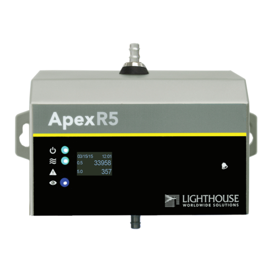
ApexRemote to four particle-size channels. Figure 2-1 shows the standard configuration as well as the optional display configuration. Table 2-1 lists features and specifics about the ApexRemote. Figure 2-1 Airborne Particle Counter ApexRemote The instrument uses a LASER diode light source and LASER beam shaping optics to illuminate a cross section of the air flow path. -
Page 16: Accessories
Lighthouse ApexRemote Operating Manual size of the particle. The voltage pulses created by the particles are then processed by additional electronics that analyze the height of each pulse and therefore the size of each corresponding particle. The result is that the number of particles of various sizes is determined. -
Page 17: Apexremote Specifications
Introduction ApexRemote Specifications 0.2 - 2.0 μm Size Range Channel Thresholds Standard 2-channel: 0.2μ, 0.3μm Standard 4-channel: 0.2μ, 0.3μ, 0.5μ, 1.0 m Optional 6-channel: 0.2μ, 0.3μ, 0.5μ, 0.7μ, 1.0μ, 2.0 m Flow Rate 0.1 CFM (2.83 LPM) Counting Efficiency 50% (per ISO 21501-4) - Page 18 Lighthouse ApexRemote Operating Manual 0.3 - 5.0 μm Size Range Channel Thresholds Standard 2-channel: 0.3μ, 0.5μm Standard 4-channel: 0.3μ, 0.5μ, 1.0μ, 5.0 m Optional 6-channel: 0.3μ, 0.5μ, 0.7μ, 1.0μ, 3.0μ, 5.0 m Flow Rate 0.1 CFM (2.83 LPM) Counting Efficiency...
- Page 19 Communication Modes MODBUS ASCII; MODBUS RTU; MODBUS ISO Probe Maximum From Inlet to ISO Kinetic Probe = ApexRemote Tubing Length 10 ft (3.0 M) Supporting Software LMS Pharma/Pro v7.3.1 or higher, LMS Express 7.5 or higher; LWS Instrument Setup Tool 1.3.5 or...
- Page 20 Lighthouse ApexRemote Operating Manual 0.3 - 5.0 μm Size Range Channel Thresholds Standard 2-channel: 0.3μ, 0.5μm Standard 4-channel: 0.3μ, 0.5μ, 1.0μ, 5.0μm Optional 6-channel: 0.3μ, 0.5μ, 0.7μ, 1.0μ, 3.0μ, 5.0μm Flow Rate 1.0 CFM (28.3 LPM) Counting Efficiency 50% (per ISO 21501-4)
- Page 21 Communication Modes MODBUS ASCII; MODBUS RTU; MODBUS ISO Probe Maximum From Inlet to ISO Kinetic Probe = ApexRemote Tubing Length 10 ft (3.0 M) Supporting Software LMS Pharma/Pro v7.3.1 or higher, LMS Express 7.5 or higher; LWS Instrument Setup Tool 1.3.5 or...
- Page 22 Lighthouse ApexRemote Operating Manual 248083447-1 Rev 1...
-
Page 23: Chapter 3 Get Started
Damaged cartons may be replaced by calling Lighthouse Sales. Keep an undamaged carton for reshipment of the instrument for its annual factory calibration. Identify the is available in two models: Serial and PoE. The ApexRemote Serial requires +24VDC to be supplied through its ApexRemote ApexRemote RJ45 connector. The... -
Page 24: Software And Smartport Cable Setup
Lighthouse ApexRemote Operating Manual Software and SmartPort cable Setup Note: 1. Place the CD into the configuration computer’s CD/DVD drive and ApexRemote instruments must use the close the tray. The CD/DVD drive should automatically start up SmartPort cable to modify and, momentarily, the Install menu will appear. - Page 25 6. Exit the Install menu. 7. The SmartPort cable can be used on all sensors and ApexRemote must be used to set the PoE ApexRemote’s IP address and all Alarm and Alarm Threshold settings. ApexRemote 8. Locate SmartPort on bottom of...
- Page 26 "see" the instrument and report an error, requiring another COM port to be selected. 13. On the configuration computer navigate to the Start menu, All Programs. Navigate to Lighthouse Worldwide Solutions, click and choose LWS Instrument Setup Tool. 248083447-1 Rev 1...
- Page 27 WARNING: Do NOT attempt to use the SmartPort cable power and power from the Serial’s RJ45 or power ApexRemote provided via the PoE port at the same time or serious damage to and support devices may occur! ApexRemote 248083447-1 Rev 1...
-
Page 28: Date Settings
Lighthouse ApexRemote Operating Manual Date Settings: This button loads computer date This button saves and time values the changes to the into program instrument memory memory Figure 3-7 Instrument Date and Time Settings Note: products can have their date and time settings... -
Page 29: Apexremote Serial
DHCP Check OFF Ethernet Check ON Alarm Settings Figure 3-8 PoE Default Settings ApexRemote Default Alarm and Threshold settings for the PoE model are the same as all models: Ch1 threshold = 1000, Ch2 threshold = ApexRemote 1000 and channel alarms are disabled. If the Alarm is enabled, the Alarm LED will turn on solid green until that Alarm’s threshold value... - Page 30 Lighthouse ApexRemote Operating Manual the same as for the PoE models. See Figure 3-9. Note Alarm Settings Figure 3-9 Serial Default Settings ApexRemote Serial address is set via the switches on the bottom ApexRemote of the instrument or through the Setup Tool program, based on Switch 7’s state (see Table 4-1 on page 4-2).
-
Page 31: Operation
Alarm LED = Threshold exceeded Blue flash = Validate mode ON White flash = SmartBracket installed but not connected to ApexRemote OFF= no alarms enabled & not in validate mode Figure 3-10 Front Panel LEDs • The green POWER LED turns on steady when the instrument is powered on and OFF when power is removed. - Page 32 Lighthouse ApexRemote Operating Manual 3-10 248083447-1 Rev 1...
-
Page 33: Chapter 4 Communications
ApexRemote ApexRemote Serial uses DIP switches to set up a portion of the ApexRemote Serial DIP ApexRemote’s functions and are shown Figure 4-1. Switches Switch 1 through 5 Figure 4-1 Serial Connectors and DIP Switch ApexRemote Refer to Table 4-1 for detailed DIP switch settings, their meaning and effects. -
Page 34: Dip Switch Definitions
Lighthouse ApexRemote Operating Manual DIP Switch Definitions Table 4-1 displays the general DIP Switch settings. OFF (UP) = 0, ON (DOWN) = 1 Note: Table 4-1 DIP Switch settings Use a tool with a very small pointed tip in order to change the DIP Position Switch positions. -
Page 35: Dip Switch Addressing
1 1 1 1 1 Communicating Serial Data / Power Port with Serial is equipped with the Serial COM Port ApexRemote ApexRemote shown in Figure 4-2 to communicate to an RS-485 network Serial incorporating LMS equipment, such as the LMS 485 Gateway and Instrument Lighthouse System Control Cabinet. - Page 36 Lighthouse ApexRemote Operating Manual Switch 1 through 5 Figure 4-2 Serial COM Port The connector pinouts are shown in Table 4-4. Table 4-4 RJ45 Pinouts RJ45 Pin Signal Name RS-232-TX (Output) RS-232 RX (Input) RESERVED for future use RS-485B RS-485A...
- Page 37 Communications RS-485 Communications RS-485 must be used if the instrument is more than 50 feet from a computer or is installed in an industrial network. Refer to Table 4-5 for specifics about RS-485. Contact Lighthouse Technical Support for more information. Table 4-5 shows the Electronics Industry Association (EIA) industry standards RS485 specifications.
-
Page 38: Communicating With Apexremote Poe Instrument
Lighthouse ApexRemote Operating Manual Communicating PoE Communications ApexRemote with PoE eliminates the need for an external power ApexRemote ApexRemote supply by getting its data and power via its connection to a PoE switch. PoE Instrument This allows a convenient installation because only one CAT6 cable is required. -
Page 39: Ethernet Settings
Communications Ethernet Settings: PoE comes with the Ethernet Enabled checkbox ApexRemote enabled (default) and the DHCP disabled. Enter the correct settings in . The IT group should provide these IP Address, Subnet, Gateway numbers to prevent conflicts with devices already on the network. All TCP/IP values should be static. -
Page 40: Apexremote Web
All diagnostic results will also be displayed. NOTE: It has been learned that certain antivirus programs may block, interrupt or seriously affect ApexRemote’s web server functions. Flow Status Service ICON... -
Page 41: Chapter 5 Maintenance Procedures
Introduction This chapter provides routine maintenance instructions that the instrument require. ApexRemote The maintenance procedures described in this chapter are not required on regular or prescribed intervals and should be performed only if the user has reason to question the data they are receiving. -
Page 42: Fault Isolation
Lighthouse. Call a Lighthouse Service Representative for assistance. Instrument The Instrument Service Report screen shows ApexRemote-specific Service and diagnostics information info. The displayed information can be saved to a pdf file by clicking the "save report" button (see Figure 5-1). -
Page 43: Chapter 6 Program With The Modbus Protocol
The ApexRx family of instruments can be programmed using the MODBUS Protocol. The full protocol, as used, is detailed in Appendix A: “ApexRemote MODBUS Register Map v1.50” on page A-1. This chapter contains the information needed to program the basic configuration for the instrument using the MODBUS protocol. -
Page 44: Running The Instrument Using Modbus
Lighthouse ApexRemote Operating Manual Running the The applicable action commands are displayed in Table 6-1. Instrument Table 6-1 Action Commands Using Value Action MODBUS Saves all writable 4xxxx register values to the EEPROM. Clears the Data Buffer. Record count is set to zero. -
Page 45: Setting The Real Time Clock
Program with the MODBUS Protocol Configuring Setting the Real Time Clock with the The Real Time Clock (RTC) can be read in registers 40027 and 40028 MODBUS as shown in Table 6-2. Protocol Register 40027 is the high word for the real time clock; 40028 is the low word. -
Page 46: Changing The Default Instrument Parameters
Lighthouse ApexRemote Operating Manual Changing the Default Instrument Parameters The main instrument parameters involved with the operation of the are Location, Sample Time and Hold Time. See Table ApexRemote 6-4. The Location is writable only when the SmartBracket is not attached and is set by writing an unsigned integer to register 40026. -
Page 47: Location (Register 40026)
Program with the MODBUS Protocol Sensor Setting Registers 40001 and 40003 through 40023 are protected and should not be changed. Location (Register 40026) For Particle Counters, this value specifies the location where a sample was recorded. Hold Time (Registers 40031, 40032) The Hold Time is used for pausing in between samples for multiple cycles. -
Page 48: Alarm Enable Registers
Lighthouse ApexRemote Operating Manual Alarm and Alarm Enable Registers Threshold The Alarm Enable input registers (43xxx series) shown in Table 6-5 are Registers read/write. All enable data items are 4 bytes long and are stored across 2 registers. Byte and word ordering is big-endian. Thus, data items are formed by placing the high bytes in front of the low bytes. -
Page 49: Enable Alarming For A Channel
The Data Status flag is set if any of the channels have a threshold exceeded state as true. Note: The threshold registers (45xxx series) shown in Table 6-8, run in ApexRemote comes standard with 2 parallel with the data registers (30xxx series). For example, data particle channels. -
Page 50: Setting The Alarm Threshold Value
Lighthouse ApexRemote Operating Manual register 30016’s threshold register would be 45016. Table 6-8 Alarm Threshold Registers Register Data Type Description 45009 unsigned int Threshold for Particle Channel 1 [high] (smallest particle size starts here) 45010 unsigned int Threshold for Particle Channel 1 [low]... -
Page 51: Chapter 7 Install
Lighthouse Worldwide Solutions. Attempting to use an under-rated power supply or cord can expose the instrument power supply, adjacent equipment or the user to dangerous shock and fire hazards. - Page 52 Lighthouse ApexRemote Operating Manual are typical for most installations. - Optional SmartBracket - Self Drilling Drywall & Stud Anchors - Phillips Screwdriver - Pen or Pencil Not shown: - Drill Motor - 3 Inch drill bit Figure 7-1 Required Tools and Hardware WARNING: 1.
- Page 53 6. For SmartBracket installation, attach the SmartBracket using the installed anchors. Make sure to use flat head screws to maintain clearance from the rear of the ApexRemote. Refer to Figure 7-4. Figure 7-4 Attach SmartBracket to Wall 248083447-1 Rev 1...
-
Page 54: Installing Apexremote Without Smartbracket
ApexRemote mounting hardware. 3. Install the mounting hardware then the ApexRemote, snugging the instrument to prevent wobble or movement while it is in use. 4. Install the necessary cable and vacuum tubing. - Page 55 1/4" ID tubing to a 1/4" barbed inlet ISO Probe. Figure 7-7 shows the bottom connections for the Serial ApexRemote and Figure 7-8 shows the bottom connections for the ApexRemote PoE. Figure 7-7 Serial Instrument Connections...
-
Page 56: Communication Ports
PoE: ApexRemote PoE uses Power over Ethernet (PoE) to provide ApexRemote the power and communications needed to operate the ApexRemote. This offers a convenient means of connecting the to an ApexRemote Ethernet network by using a CAT6 patch cable. If PoE power is not... -
Page 57: Smartbracket Settings
SmartBracket Settings When the is attached to a SmartBracket, enable the ApexRemote SmartBracket by placing a checkmark in the Enable box or remove the checkmark to disable the attached SmartBracket. Disabling the SmartBracket will drop its unique ID from the network and from any monitoring software display/status. -
Page 58: Realtime Lms Pro/Pharma Data Download
Lighthouse ApexRemote Operating Manual Realtime LMS Lighthouse offers several software products to download, monitor and manage data gathered by the instruments, as well as Pro/Pharma ApexRemote other RS-485/MODBUS particle counters. When these instruments are Data connected to an RS-485 or ethernet network that is monitored and... -
Page 59: Appendix A Apexremote Modbus Register Map V1.50
ApexRemote MODBUS Register Map v1.50 COMM Lighthouse particle counters with MODBUS use the following Settings communications settings: Table A-1 MODBUS Communications Settings Baud Rate 19200 Data Bits Stop Bits Parity None Hardware Protocol RS-232-C or RS-485 standard Software Protocol MODBUS ASCII (supports upper/lower case) -
Page 60: Sensor Settings Registers
Lighthouse ApexRemote Operating Manual Register Map Sensor Settings Registers Instrument settings are stored in holding registers (the 40xxx series), which are mostly read/writable. Not all holding registers are writable. Table A-3 describes the content of these registers. Table A-3 Sensor Settings Registers... - Page 61 ApexRemote MODBUS Register Map v1.50 Table A-3 Sensor Settings Registers Register Data Type Description 40021 ASCII string Model Name char[12], char [13] 40022 ASCII string Model Name char[14], char [15] 40023 unsigned integer Flow Rate. See registers 40041-40042 for flow rate units.
-
Page 62: Device Options
Lighthouse ApexRemote Operating Manual Table A-3 Sensor Settings Registers Register Data Type Description 40035 unsigned integer Data Set [high]. Works in conjunction with 40036. Updates the instrument’s real time clock. Setting is the number of seconds since midnight, 1/1/1970. This number can be generated by the ANSI C/C++ time() function. - Page 63 ApexRemote MODBUS Register Map v1.50 Table A-3 Sensor Settings Registers Register Data Type Description 40060 signed integer Last Sample Timestamp [high] (# of seconds since midnight, 1/ 1/1970.). 40061 signed integer Last Sample Timestamp [low]. 40062 signed integer Last Setting Change Timestamp [high] (# of seconds since midnight, 1/1/1970.).
-
Page 64: Device Status
Lighthouse ApexRemote Operating Manual Table A-3 Sensor Settings Registers Register Data Type Description 40074 signed integer ApexRemote: Last Calibration Date [high]. Indicates when instrument was last calibrated. This number can be generated by the ANSI C/ C++ time() function. 40075... - Page 65 ApexRemote MODBUS Register Map v1.50 Table A-5 Device Status Status (40003/40057) Description NEW DATA: Set to 1 to indicate that a new data record has been recorded and it hasn't been read via modbus yet. When a data record has been read via modbus (registers 30001 to 30999), then this flag is reset to zero.
- Page 66 Lighthouse ApexRemote Operating Manual Table A-6 Device Status Status (40056) Description ApexRemote: LASER CURRENT STATUS: Set to 1 when unit’s LASER power is out of spec, else set to 0 ApexRemote: LASER SUPPLY STATUS: Set to 1 when unit’s LASER supply is out of spec, else set to 0 ApexRemote: LASER LIFE STATUS: Set to 1 when unit’s LASER...
- Page 67 ApexRemote MODBUS Register Map v1.50 response. When this register is read, it always returns a zero. Table A-7 Command Register Value Action Saves all writable 4xxxx register values to the EEPROM. Reserved for future use. Clears the Data Buffer. Record count is set to zero.
-
Page 68: Alarm Enable Registers
Lighthouse ApexRemote Operating Manual Alarm and Alarm Enable Registers Threshold The Alarm Enable input registers (43xxx series) are read/write. All Registers enable data items are 4 bytes long and are stored across 2 registers. Byte and word ordering is big-endian. Thus, data items are formed by placing the high bytes in front of the low bytes. -
Page 69: Enable Alarming For A Channel
ApexRemote MODBUS Register Map v1.50 Table A-9 Alarm Enable Registers Register Data Type Description 43015 unsigned int Alarm Enable for Particle Channel 4 [high] 43016 unsigned int Alarm Enable for Particle Channel 4 [low] Enable Alarming for a Channel To enable alarming on particle channel #1, write a ’3’ to register 43010, which enables its Bit 1 and maintains Bit 0 as ’1’. -
Page 70: Setting The Alarm Threshold Value
Lighthouse ApexRemote Operating Manual Note: The Data Status flag is set if any of the channels have a threshold The Table A-11 shows the registers for an exceeded state as true. 8 channel particle counter. Counters with fewer The threshold registers (45xxx series) run in parallel with the data channels do not use the registers (30xxx series). - Page 71 ApexRemote MODBUS Register Map v1.50 placing the high bytes in front of the low bytes. Example: <High Bytes><Low bytes> = <4 Byte Data Item> Not all particle and analog channels are active. Retrieving data from an inactive channel returns garbage. See the Data Enable Registers section of this document for details on how to record data from active channels.
- Page 72 IEEE float LASER Supply [high] (percentage based on LASER Supply Reference Value. 30065 IEEE Float Background Voltage [low] (percentage based on Calibration Reference value) - ApexRemote 30066 IEEE Float Background Voltage [high] 30069 IEEE Float LASER Voltage [low] (Percentage based on...
- Page 73 ApexRemote MODBUS Register Map v1.50 Table A-14: Instrument Current Status Value Action Particle Overflow Status 0 = No overflow 1 = Overflow occurred. Instrument Service Status 0 = Instrument is working correctly. 1 = Service light is on. Instrument malfunction detected.
-
Page 74: Device Status Word
Lighthouse ApexRemote Operating Manual Table A-14: Instrument Current Status Value Action ApexRemote: Photodiode health status 0 = Photodiode good. 1 = Photodiode failure ApexRemote: Validation mode status 0 = Normal operation data. 1 = Validation dummy data. ApexRemote: Calibration due date status 0 = Unit has not passed calibration date. -
Page 75: Data Enable Registers
ApexRemote MODBUS Register Map v1.50 Table A-15 Device Status Word Description Particle Threshold Exceeded Status 0 = Threshold not exceeded 1 = Threshold exceeded Data Enable Registers Note: The 31xxx register series is used to determine which data items in... - Page 76 Lighthouse ApexRemote Operating Manual A-18 248083447-1 Rev 1...
-
Page 77: Appendix B Limited Warranty
STRICT LIABILITY, OR PRODUCT LIABILITY CLAIM AND BUYER AGREES TO WAIVE SUCH CLAIMS. LWS’s SOLE AND EXCLUSIVE LIABILITY AND BUYERS SOLE Lighthouse Worldwide Solutions (LWS) warrants that all AND EXCLUSIVE REMEDY, FOR ANY equipment shall be free from defects in material and... - Page 78 Lighthouse ApexRemote Operating Manual 248083447-1 Rev 1...
- Page 79 Antivirus programs and web server fail 4-8 Default Alarm Threshold ApexRemote instrument 2-1 PoE 3-7 ApexRemote PoE COM Port 7-6 Serial 3-7 ApexRemote PoE Default Alarm Threshold 3- Default Instrument Parameters Changing 6-4 ApexRemote Serial Default Alarm Threshold Default PoE Factory IP 3-6 Device Status A-6...
- Page 80 Lighthouse ApexRemote Operating Manual Realtime LMS Pro/Pharma Data Download 7-8 Register Map A-2 Remote02 Calibration 2-3 Initial Inspection 3-1 Remote02 Channel Thresholds 2-3 instrument 2-1 Remote02 Communication Modes 2-3 Instrument Current Status A-14 Remote02 Counting Efficiency 2-3 Interruption of webserver 4-8...
- Page 81 Index Remote05 Power Supply Specifications 2-5 Remote05 Size Range 2-5 Remote05 Storage Temp/RH 2-5 Safety 1-1, 5-1 Remote05 Supporting Software 2-5 Electrostatic safety information 1-2 Remote05 Weight 2-5 Laser safety information 1-1 Remote05 Zero Count Level 2-5 Sample Time 6-5 Remote3 Calibration 2-6 Save 6-2 Remote3 Channel Thresholds 2-6...
- Page 82 Lighthouse ApexRemote Operating Manual Zero Count Check Troubleshooting 5-2 Zero Count Test 5-1 248083447-1 Rev 1...
Need help?
Do you have a question about the ApexRemote and is the answer not in the manual?
Questions and answers