Table of Contents
Advertisement
Quick Links
BOS1211-KIT
User Guide – Preliminary
1 Features
•
Plug and play development kit to experience
piezo haptic feedback
•
Low-power BOS1211 integrated circuit, high
voltage driver with digital interface
•
Easy generation of high-voltage waveforms
up to 120 V
•
Enable sensing and emulate button behavior
using the actuator
•
Three miniature PCB slots for scalable
BOS1211 driver boards
•
Compatible with big piezoelectric actuators
such as TDK PowerHap
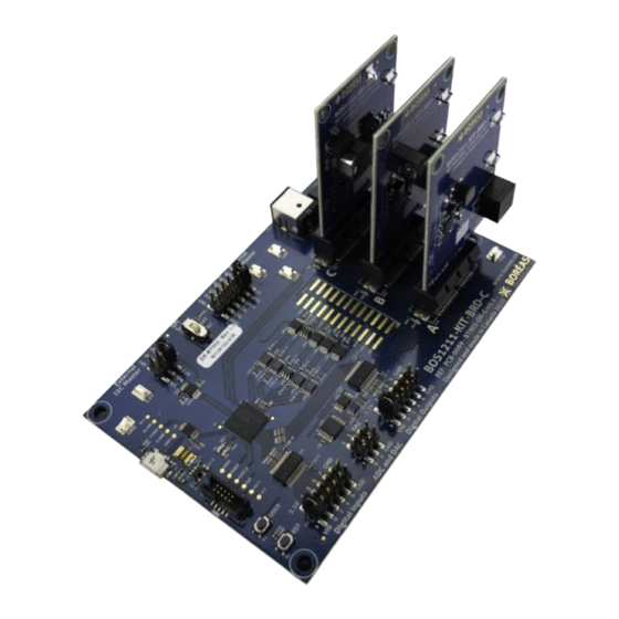
Figure 1: BOS1211-KIT Overview
1
PowerHap™ is a trademark of TDK Corporation.
BT002BDK01.05 – Issue 5
CONFIDENTIAL
BOS1211 Development Kit
TM 1
120 V models.
© All rights reserved 2020 Boréas Technologies Inc
2 Description
The BOS1211-KIT is a Development Kit to help
users get familiar with the BOS1211 Piezo Haptic
Driver IC.
Miniature PCBs are interchangeable allowing the
users to experiment with the actuator sizes
adapted to their platform.
This kit connects to associated PC software over
USB for easy programming of the BOS1211 and
manual generation of waveforms on the
connected actuator.
The piezoelectric actuator sensing capability is
used to emulate a button behavior. The sensing
and feedback parameters can be changed using
the software.
Many GPIOs and hardware features are accessible
to ease prototype building.
Table 1: Ordering information
PRODUCT
DESCRIPTION
BOS1211-KIT-B
Starter Set with one actuator
For details see section 10.
1
Advertisement
Table of Contents

Related Manuals for Boreas Technologies BOS1211


Summary of Contents for Boreas Technologies BOS1211
- Page 1 BOS1211 Development Kit 1 Features 2 Description • Plug and play development kit to experience The BOS1211-KIT is a Development Kit to help piezo haptic feedback users get familiar with the BOS1211 Piezo Haptic • Low-power BOS1211 integrated circuit, high Driver IC.
-
Page 2: What's In The Box
BOS1211-KIT CONFIDENTIAL User Guide – Preliminary 3 Quick-Start Guide 3.1 What's in the Box The content of the BOS1211-KIT is given in the following table. Table 2: Starter Set BOS1211-KIT-B development kit content # ITEM DESCRIPTION REFERENCE Controller board BOS1211-BRD-C controller evaluation board. - Page 3 BOS1211-KIT CONFIDENTIAL User Guide – Preliminary # ITEM DESCRIPTION REFERENCE TDK Piezo Actuator TDK PowerHap™ 1919H021V120 (25G) Actuator Ordering: Z63000Z2910Z 1Z43 Capacitance : 2.5 μF Dim : 19.4 x 19.4 x 2.1 mm 12 V Power Supply Power supply to provide 12 V to the Evaluation PCB.
-
Page 4: Board Overview
Slot Card A Digital ADC & Digital B OS1211-K I T- Inputs Outputs www.bor eas.ca B R D -C Mount hole Figure 3: BOS1211-KIT-BRD-C controller board overview BT002BDK01.05 – Issue 5 © All rights reserved 2020 Boréas Technologies Inc... -
Page 5: Quick-Start Procedure
Important Note: this evaluation kit does not support hot swapping the driver boards in or out of the controller board. 1. When shipped the BOS1211-KIT-BRD-C is already loaded with the appropriate firmware. If the firmware needs updating, see section 5.4. - Page 6 The larger BOS1211-KIT-BRD-C is the main controller board. The smaller BOS1211-KIT-BRD-S, BOS1211-KIT-BRD-M and BOS1211-KIT-L driver boards must be inserted in one of the three card sockets. They may be inserted in any order. Not all sockets need to be populated.
- Page 7 User Guide – Preliminary 4.2 Changing the Miniature Driver Boards BOS1211 board components can be scaled depending on the piezoelectric actuator used. Each driver board (BOS1211-KIT-BRD-S, BOS1211-KIT-BRD-M and BOS1211-KIT-L) has been designed with components to support various actuator sizes. The table below indicates which driver board is best suited depending on the actuator capacitance.
-
Page 8: Compatible Firmware
BOS1211-KIT CONFIDENTIAL User Guide – Preliminary 4.3 Identifying the Boards Revision Number Each PCB board reference design and revision number (v#.#) are identified next to the “REF:” label. The following table indicates compatibility with the firmware and Devkit Controller software. - Page 9 SCK, MISO and MOSI connections are shared by all BOS1211 on the driver boards. Three chip selects (CSA, CSB and CSC) are required to access the chip select pin on each BOS1211 in the slots A, B and C. By default, a jumper on 5 V and VSPI forces the internal 5 V supply to be used. To use an external voltage domain, remove this jumper and connect VSPI to the external supply.
- Page 10 USER is not used by the current firmware. 4.4.8 LED A total of 5 LEDs are present on the development kit BOS1211-KIT-BRD-C board. D1 (green LED) and D2 (red LED) are located near the USB connector. They indicate firmware revision during boot up and provide information on development kit operation.
-
Page 11: Led Indicators
VIN too low (UVLO12) VIN too high (OVLO12) Short-circuit detected between VOUT and VIN (SC) For more information on the status error, please refer to the BOS1211 datasheet. 5.3 Modes of Operation 5.3.1 PC Connected When the board is connected to a PC running the Boréas DevKit Controller software, it will communicate with it and the user can control the board using the software interface. - Page 12 5.4.1 Kits Shipped with Firmware Revision Prior to 1.5.0 The BOS1211-KIT is provided out of the box with a firmware for use as USB Serial Device. This firmware can be changed and/or updated using the dfuh-tool.exe application available on Boréas website.
- Page 13 BOS1211-KIT CONFIDENTIAL User Guide – Preliminary Figure 5: dfuh-tool.exe for firmware installation/update BT002BDK01.05 – Issue 5 © All rights reserved 2020 Boréas Technologies Inc...
- Page 14 BOS1211-KIT CONFIDENTIAL User Guide – Preliminary 5.4.2 Kits with Firmware Revision Installed is 1.5.0 or later The following procedure applies to kits shipped with firmware revision 1.5.0 or later installed. It will also apply to previous kits once the firmware has been updated to revision 1.5.0 or later.
-
Page 15: Software Installation
6.2 Using the Application 6.2.1 Overview Boréas DevKit Controller is a graphical user interface (GUI) intended to ease evaluation of the BOS1211 IC. Using this application, users can easily trigger waveforms manually or using a system I/O, activate sensing and monitor the IC state. - Page 16 BOS1211-KIT CONFIDENTIAL User Guide – Preliminary is not compatible with the PC software, the user will have the opportunity to automatically update the firmware. About This button opens the About box giving information about the application. Exit This button closes the application.
-
Page 17: Basic Tab
For the selected mini-board tab, the Basic tab is used to send waveforms to the evaluation board. This section describes each parameter and control. Sync/Desync All Button When pressed, all connected boards will play the same waveform using BOS1211 SYNC feature. Depress the button to play waveforms on individual boards. Save in Memory This button will save the current configuration to the MCU internal memory. - Page 18 BOS1211-KIT CONFIDENTIAL User Guide – Preliminary Figure 8 Main application window when connected - Basic tab Sensing When checked, the actuator will behave like a button, playing the waveform when pressed and released. The release waveform amplitude is set to 75% of the press waveform amplitude. This box must first be checked to adjust the sensing parameters.
- Page 19 BOS1211-KIT CONFIDENTIAL User Guide – Preliminary Direction Direction the voltage is crossing the threshold for a detection to be successful. Using TDK PowerHap actuators, the direction of a press event should be upward and that of a release event should be downward.
-
Page 20: Registers Tab
BOS1211-KIT CONFIDENTIAL User Guide – Preliminary 6.2.6 Registers Tab The Registers Tab allows to monitor the register content of the selected connected mini-board. It also allows to write specific values to any writeable registers on the driver IC by clicking the Send button next to that register. - Page 21 BOS1211-KIT CONFIDENTIAL User Guide – Preliminary 7 Design Reference 7.1 Schematics Figure 11: BOS1211-KIT-BRD-C Schematic part 1 - SWD and microcontroller- Revision 1.1 BT002BDK01.05 – Issue 5 © All rights reserved 2020 Boréas Technologies Inc...
- Page 22 BOS1211-KIT CONFIDENTIAL User Guide – Preliminary Figure 12: BOS1211-KIT-BRD-C Schematic part 2 – USB and Connectors- Revision 1.1 Figure 13: BOS1211-KIT-BRD-C Schematic part 3 – Inputs and outputs- Revision 1.1 BT002BDK01.05 – Issue 5 © All rights reserved 2020 Boréas Technologies Inc...
- Page 23 User Guide – Preliminary Figure 14: BOS1211-KIT-BRD-C Schematic part 4 – External I2C Master- Revision 1.1 Figure 15: BOS1211-KIT-BRD-C Schematic part 5 – ADC and DAC - Revision 1.1 BT002BDK01.05 – Issue 5 © All rights reserved 2020 Boréas Technologies Inc...
- Page 24 BOS1211-KIT CONFIDENTIAL User Guide – Preliminary Figure 16: BOS1211-KIT-BRD-C Schematic part 6 – Mini-board ID- Revision 1.1 Figure 17: BOS1211-KIT-BRD-C Schematic part 7 - SPI- Revision 1.1 BT002BDK01.05 – Issue 5 © All rights reserved 2020 Boréas Technologies Inc...
- Page 25 BOS1211-KIT CONFIDENTIAL User Guide – Preliminary Figure 18: BOS1211-KIT-BRD-C Schematic part 1 – 12 V supply and slot card connectors- Revision 1.1 BT002BDK01.05 – Issue 5 © All rights reserved 2020 Boréas Technologies Inc...
- Page 26 BOS1211-KIT CONFIDENTIAL User Guide – Preliminary Figure 19: BOS1211-KIT-BRD-S Schematic – Revision 1.3 BT002BDK01.05 – Issue 5 © All rights reserved 2020 Boréas Technologies Inc...
- Page 27 BOS1211-KIT CONFIDENTIAL User Guide – Preliminary Figure 20: BOS1211-KIT-BRD-M Schematic – Revision 1.3 BT002BDK01.05 – Issue 5 © All rights reserved 2020 Boréas Technologies Inc...
- Page 28 BOS1211-KIT CONFIDENTIAL User Guide – Preliminary Figure 21: BOS1211-KIT-BRD-L Schematic – Revision 1.3 BT002BDK01.05 – Issue 5 © All rights reserved 2020 Boréas Technologies Inc...
-
Page 29: Pcb Layout
BOS1211-KIT CONFIDENTIAL User Guide – Preliminary 7.2 PCB Layout Figure 22: BOS1211-KIT-BRD-C Layout top view- Revision 1.1 Figure 23: BOS1211-KIT-BRD-C Layout bottom view (mirrored) - Revision 1.1 BT002BDK01.05 – Issue 5 © All rights reserved 2020 Boréas Technologies Inc... - Page 30 BOS1211-KIT CONFIDENTIAL User Guide – Preliminary Figure 24: BOS1211-KIT-BRD-S/M/L Layout top view – Revision 1.3 Figure 25: BOS1211-KIT-BRD-S/M/L Layout bottom view – Revision 1.3 BT002BDK01.05 – Issue 5 © All rights reserved 2020 Boréas Technologies Inc...
-
Page 31: Bill Of Materials
PCB. If the exact part number is not available, the components can be replaced by ones with equivalent package and specifications. Table 6: Bill of Materials – BOS1211-KIT-BRD-C – Revision 1.1 DESIGNATOR VALUE... - Page 32 BOS1211-KIT CONFIDENTIAL User Guide – Preliminary DESIGNATOR VALUE DESCRIPTION MANUFACTURER PART NUMBER Cypress IC DUAL CORE MCU 32B 1M 124BGA Semiconductor CY8C6137BZI-F34 Corp IC REG LINEAR 3.3V 200MA SOT23-5 Texas Instruments TPS79333DBVR U21, U22 IC TRNSLTR BIDIRECTIONAL 24SSOP Texas Instruments...
- Page 33 BOS1211-KIT CONFIDENTIAL User Guide – Preliminary Table 7: Bill of Materials – BOS1211-KIT-BRD-S/M/L – Revision 1.3 DESIGNATOR* VALUE DESCRIPTION MANUFACTURER PART NUMBER C1-1, C1-2, C1-3, C2-1, 0.1µF CAP CER 0.1UF 25V X5R 0402 Taiyo Yuden TMK105BJ104KVF C2-2, C2-3, C3-1, C3-2,...
-
Page 34: Faq And Troubleshooting
0x32 value instead of the expected 0x30 value. If this is the case, then 0xE400 need to be sent on the SPI interface to the BOS1211. Then the CHIP needs to be checked again for verification. Once it outputs 0x30, normal execution may continue. -
Page 35: Notice And Warning
The piezoelectric actuator is connected between OUT and VIN. When measuring these signals using an oscilloscope, use a separate probe on each terminal of the actuator. Never connect the ground of a probe to one of these terminals. Doing so might damage the BOS1211-KIT and/or your oscilloscope. BT002BDK01.05 – Issue 5... -
Page 36: Ordering Information
BOS1211-KIT CONFIDENTIAL User Guide – Preliminary 10 Ordering Information Table 8: Ordering information ORDERABLE PACKING STANDARD ROHS ACTUATORS DEVICE FORMAT QUANTITY COMPLIANT BRD-C 120 x 80 mm 1/box TDK PowerHap BOS1211-KIT-B 3 Channels 17 x 17 x 3 cm. 1919H021V120...
Need help?
Do you have a question about the BOS1211 and is the answer not in the manual?
Questions and answers