Table of Contents
Advertisement
Quick Links
BOS1901-KIT
User Guide
1 Features
•
Plug and play development kit to experience
piezo haptic feedback
•
Low-power BOS1901 integrated circuit, high
voltage driver with digital interface
•
Simple power interface for development via
USB port
•
Standard USB audio to prototype haptic
effects in MATLAB®, Python®, Audacity® and
many other softwares
•
Fully embeddable modular software driver
•
Easy generation of high-voltage waveforms
up to 190 Vpp
•
Two breakable miniature PCBs with BOS1901
drivers
•
Standard
commercial
included in the Kit:
o
Starter Set: TDK PowerHap™ 1204
o Premium Set: TDK PowerHap™ 1204
lateral, 0904 lateral, 0909 square, Midé
Technology PPA-2014 bending.
1
MATLAB® is registered trademark of The MathWorks, Inc.
Python® is a registered trademark of the PSF
BOS1901CDK01.2
BOS1901 Development Kit
1
piezo
actuators
2
lateral
External
PSU
SWD
Microcontroller
USB
DIP
Switches
Figure 1: Simplified BOS1901-KIT diagram
© All rights reserved 2019 Boréas Technologies Inc
2 Description
The BOS1901-KIT is a Development Kit to help
users who want to get familiarized with the
BOS1901 Piezo Haptic Driver IC.
The USB powered kit appears as an USB Audio
device for the computer, which allows the rapid
generation of waveforms using existing audio
software like Audacity® for haptic prototyping.
Each breakable miniature PCB gives access to all
signals allowing the user to experiment with the
BOS1901 using a development platform of his/her
choice.
Standard commercial piezo actuators are provided
as a starting point to begin experiencing with
haptic feedback.
Table 1: Ordering information
PRODUCT
DESCRIPTION
BOS1901-KIT-A
Premium Set with Four Actuators
BOS1901-KIT-B
Starter Set with One Actuator
For details see section 2
BOS1901
breakable PCB
Channel A
SPI
BOS1901
breakable PCB
Channel B
2
PowerHap™ is a trademark of TDK Corporation
Audacity® is a registered trademark of Dominic Mazzoni
1
Advertisement
Table of Contents

Related Manuals for Boreas Technologies BOS1901


Summary of Contents for Boreas Technologies BOS1901
- Page 1 BOS1901-KIT User Guide BOS1901 Development Kit 2 Description 1 Features The BOS1901-KIT is a Development Kit to help • Plug and play development kit to experience users who want to get familiarized with the piezo haptic feedback BOS1901 Piezo Haptic Driver IC.
-
Page 2: What's In The Box
User Guide 3 Quick-Start guide 3.1 What's in the Box The BOS1901-KIT is currently available in two distinct packages: Premium Set and Starter Set. The following tables show the content of each set. Table 2: Premium Set BOS1901-KIT-A development kit content... - Page 3 BOS1901-KIT User Guide Table 3: Starter Set BOS1901-KIT-B development kit content # ITEM DESCRIPTION REFERENCE Evaluation PCB BOS1901 Evaluation PCB USB Cable Cable to connect the evaluation PCB to a computer Stewart Connector part number SC-2AMK001F TDK Piezo Actuator TDK Mini PowerHap™ 1204H018V060 (4.5G) Actuator...
-
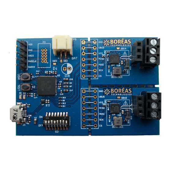
Page 4: Pcb Overview
2018 BOS1901-KIT_V2.3 www.boreas.ca CHANNEL B Figure 2: BOS1901-KIT Evaluation PCB overview 3.3 Quick-Start Procedure 1. Refer to sections 4.1 for jumper options and 4.2 for switch settings to insure the evaluation PCB is in the intended settings. 2. Connect the selected actuator to channel A on P2A connector (refer to sections 4.2 and 4.4). -
Page 5: Jumper Options
BOS1901-KIT User Guide 4 Hardware 4.1 Jumper Options The BOS1901-KIT is provided by default with jumpers SB2, SB3 and SB1X set to operate from USB power, UPI mode off. Table 4: Jumper options Function Shorts USB Power UPI OFF (default) - Page 6 (see section 6.1). 4.2 Piezo Actuators One TDK actuator is provided with the BOS1901-KIT Starter Set and four with the Premium Set, one from Midé and the others from TDK. 4.2.1 Midé Actuator Midé...
- Page 7 -10 V and +60 V. Example waveforms are provided on Boréas website (www.boreas.ca/bos1901-kit). Refer to section 4.4.2 for a special output configuration, in which two TDK actuators can be connected on a single BOS1901 circuit: "Load 1"...
- Page 8 BOS1901-KIT User Guide 4.2.3 Midé Actuator Clamp Assembly Instructions The Midé actuator must be assembled the provided clamp to be operated properly. Follow the instructions below to assemble the clamp on the actuator. 1. Take Midé actuator, black clamp, screw and 2.
-
Page 9: Dip Switch Settings
BOS1901-KIT User Guide 4.3 DIP Switch Settings The evaluation PCB is provided by default with S3 DIP Switch set to Unipolar operation with only Channel A enabled. It is recommended to toggle these switches only while not playing waveforms. Table 5: S3 DIP switch settings... - Page 10 BOS1901-KIT User Guide pressure triggers a single light click, medium pressure triggers a stronger click, and a high pressure triggers a longer feedback. SW5 sets the frequency of the feedback response when the actuator is pressed and released. SW6 sets the amplitude level of the feedback response. Setting SW6 to ON will provide a stronger response than setting it to OFF.
- Page 11 BOS1901-KIT User Guide 4.4 Output Configuration Options With the two-terminal differential output, two outputs configurations are possible to drive a piezo. 4.4.1 Differential Output Configuration The typical output configuration is the differential output, refer to Figure 4. The piezo-element is driven with one terminal connected to "HV+"...
- Page 12 MOSI SPI Master Out/Slave In signal SPI Clock signal SPI Chip Select signal (active low) Refer to BOS1901 datasheet for a complete description on how to use and program the circuit. BOS1901CDK01.2 © All rights reserved 2019 Boréas Technologies Inc...
-
Page 13: Software Installation Procedure
1. Connect the evaluation PCB with the USB cable, wait for green LED to light up and for red LED to turn and stay off, after the firmware identification sequence (see section 6.1). 2. Start Audacity®, then select "File/Open…" to load "Audacity project - BOS1901-KIT.aup" file available for download on Boréas... - Page 14 BOS1901-KIT User Guide 6. The balance between channels A and B can be changed using the "L/R" dial in the "Audio Track" field, "L" corresponding to channel A, "R" to channel B. The gain can also be changed with "-/+"...
- Page 15 LED will flash to indicate channel A BOS1901 IC revision, and red LED will flash to indicate channel B BOS1901 IC revision. For each channel, the LEDs will flash 1, 2 or 3 times to indicate the IC for that channel is of revision A, B or C respectively.
- Page 16 BOS1901-KIT User Guide Figure 7: USBBootloaderHost.exe interface for firmware installation/update BOS1901CDK01.2 © All rights reserved 2019 Boréas Technologies Inc...
- Page 17 BOS1901. This section only presents a starting point for any user who may want to modify the firmware. A careful read of the BOS1901 datasheet is strongly recommended before doing so.
- Page 18 6.4 Adjusting Sensing Feedback Parameters via Firmware Modification The BOS1901-KIT is provided out-of-the box with a firmware that allows sensing feedback to be experienced (see section 3.3). S3 DIP Switches SW4 to SW7 can be used to toggle the sensing feedback parameters between preset values (see section 4.3).
- Page 19 3. Save and build the project, and then upload the new firmware as explained in section 6.2 or using a MiniProg3. Note: Since firmware v2.3, the “USR” button is used to return all parameters programmed using BOS1901-KIT Controller GUI software to their default value. BOS1901CDK01.2 © All rights reserved 2019 Boréas Technologies Inc...
- Page 20 The GUI installer is available for download on Boréas website. Any advices on the installation procedure and on how to use it will be found in the BOS1901-KIT Controller (GUI) – User Guide also provided on the website. Figure 8: BOS1901-KIT Controller GUI – Main Window BOS1901CDK01.2...
- Page 21 BOS1901-KIT User Guide 8 Design Reference 8.1 Schematics Figure 9: Schematic part 1 - USB and microcontroller BOS1901CDK01.2 © All rights reserved 2019 Boréas Technologies Inc...
- Page 22 BOS1901-KIT User Guide Figure 10: Schematic part 2 - BOS1901 BOS1901CDK01.2 © All rights reserved 2019 Boréas Technologies Inc...
-
Page 23: Pcb Layout
BOS1901-KIT User Guide 8.2 PCB Layout Figure 11: Layout view - Top Overlay (not to scale) Figure 12: Layout view - Top Layer (not to scale) BOS1901CDK01.2 © All rights reserved 2019 Boréas Technologies Inc... - Page 24 BOS1901-KIT User Guide Figure 13: Layout view - Bottom Layer (mirrored, not to scale) Figure 14: Layout view - Bottom Overlay (mirrored, not to scale) BOS1901CDK01.2 © All rights reserved 2019 Boréas Technologies Inc...
-
Page 25: Bill Of Materials
BOS1901-KIT User Guide 8.3 Bill of Materials The following is a list of the components that populate the evaluation PCB. Due to availability, some components with equivalent performance/characteristics may be installed on the actual evaluation PCB. If the exact part number is not available, the components can be replaced by ones with equivalent package and specifications. -
Page 26: Faq And Troubleshooting
Please refer to Boréas website for FAQ and Troubleshooting information, which will be maintained throughout the BOS1901-KIT lifecycle. It will also contain application note documents that will be helpful for the user writing his/her own code to operate the BOS1901. -
Page 27: Ordering Information
Midé PPA-2014 Bending 1/box BOS1901-KIT-B TDK PowerHap™ 1204 Lateral 64x48mm 2 Channels Prod (Starter Set) (4x2x1)” (35x24) 1 Actuator 12 Document History ISSUE DATE CHANGES July 2019 Updated BOS1901-KIT ordering options. BOS1901CDK01.2 © All rights reserved 2019 Boréas Technologies Inc... - Page 28 BOS1901-KIT User Guide BOREAS TECHNOLOGIES INC STANDARD TERMS FOR DEVELOPMENT KIT PRIOR TO USING THE DEVELOPMENT KIT, USER MUST REVIEW THE USER DOCUMENTATION PROVIDED ON BOREAS.CA INCLUDING THE FULL VERSION OF BOREAS STANDARD TERMS AND CONDITIONS. DELIVERY 1.1 BORÉAS TECHNOLOGIES (“BORÉAS”) delivers BORÉAS Development Kits including any accompanying demonstration software, components, and/or documentation which may be provided together or separately (collectively, an “DEV.KIT”) to the User (“User”) in...
- Page 29 BOS1901-KIT User Guide 4.3.2 DEV.KITs are intended solely for use by technically qualified, professional electronics experts who are familiar with the dangers and application risks associated with handling electrical mechanical components, systems, and subsystems. User assumes all responsibility and liability for proper and safe handling and use of the DEV.KIT by User or its employees, affiliates, contractors or designees. User assumes all responsibility and liability to ensure that any interfaces (electronic and/or mechanical) between the DEV.KIT and any human body are...
- Page 30 BOS1901-KIT User Guide BOREAS TECHNOLOGIES INC WARNING EXPORT NOTICE Recipient agrees to not knowingly export or re-export, directly or indirectly, any product or technical data (as defined by the Canada, U.S., EU, and other Export Administration Regulations) including software, or any controlled product restricted by other applicable national regulations, received from BORÉAS TECHNOLOGIES under this Agreement, or any direct product of such technology, to any destination to...
Need help?
Do you have a question about the BOS1901 and is the answer not in the manual?
Questions and answers