Table of Contents
Advertisement
Available languages
Available languages
Advertisement
Table of Contents

Summary of Contents for Sit 840 SIGMA
- Page 1 8 4 0 S I G M A ENGLISH - ITALIANO Read the instructions before use. This control must be installed in accordance with the rules in force Leggere le istruzioni prima dell’uso. Questo controllo deve essere installato in accordo con le normative in vigore...
- Page 3 English Italiano...
-
Page 4: Main Features
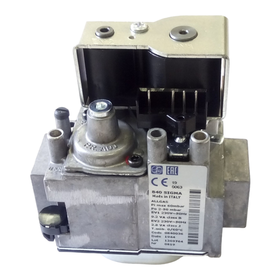
Multifunctional gas control with double safety solenoid and servo-assisted gas outlet pressure regulator. The control is designed for use in appliances with automatic ignition and flame detection systems, with direct burner ignition or intermittent pilot. All the adjustments can be made from the top face and it is suitable for all three gas families. DESCRIPTION On-off solenoid valve EV1 On-off solenoid valve EV2... -
Page 5: Technical Data
Power at nominal voltage ( (AC) (mA) 230 V 50 Hz 24 V 50 Hz Protection degree: IP 40 with SIT NAC 504 connector. IP 44 with SIT NAC 504 connector and gasket IP 40 or IP 44 with connectors 960.4 serie... - Page 6 GAS FLOW Solenoid valves class B+J Flow Q as a function of pressure, drop ∆ P Q [m 3 /h d=0.55] Flowrate at ∆ P = 5 mbar Gas Family Class B+J d=0.41 d=0.55 d=1.55 3.6 m ∆ P [mbar] Regulated flow Q Solenoid valves class B+J as a function to outlet pressure Pu,...
-
Page 7: Installation
(sec.) INSTALLATION SIT 840 SIGMA complied with current safety standards. Nevertheless, its installation on appliances must be verified in accordance with the specific standards for each installation. In particular, it is necessary to ensure that requirements relating to the class of flame failure device, automatic shut-off valve and pressure regulator are met. - Page 8 Apply the proper torque to the locking ring, according to the washer characteristics, in order to ensure the seal. : do not over-tighten the locking ring. WARNING - Connection with union joint (B) Use SIT joint 0.982.001. Ensure the locking ring is properly engaged. Recommended torque range 40-60 Nm. Do not overtorque.
-
Page 9: Electrical Connections
Flange connections (flanges shall be according ISO 7005) First screw the pipes into the flanges and then the flanges to the multifunctional control. Recommended torque for flange retaining screws: 3 Nm. Caution: check the”0” ring is properly placed in the groove of the flange. Rp 1/2 connection Prevent foreign matter from getting into the valve during installation. -
Page 10: Settings And Adjustments
SETTINGS AND ADJUSTMENTS All adjustments must be made on the basis of the specific characteristics of the appliance. Check inlet and outlet pressure using the pressure test points provided. After testing, carefully seal test points with the provided screws. Recommended torque: 1.0 Nm. Adjusting the outlet pressure All the adjustments must be carried out in the following order: Check the inlet P... - Page 11 Gas connection: G3/4 ISO 228...
- Page 12 Gas connection: Flanges...
- Page 13 SLOW OPENING VERSION - Gas connection: G3/4 ISO 228...
- Page 14 SLOW OPENING VERSION - Gas connection: Flanges...
-
Page 15: Caratteristiche Principali
Controllo multifunzionale dotato di due elettrovalvole di sicurezza e operatore modulante per la regolazione automatica della pressione in uscita. Il controllo è destinato per uso in applicazioni con sistemi ad accensione automatica, con accensione diretta del bruciatore o pilota intermittente. Tutte le regolazioni sono accessibili sulla parte superiore ed è... -
Page 16: Dati Tecnici
Corrente a regime Potenza ( (AC) (mA) 230 V 50 Hz 24 V 50 Hz Grado di protezione: IP 40 con connettore SIT NAC 504. IP 44 con NAC 504 e guarnizione IP 40 e IP 44 con connettori serie 0.960.4... - Page 17 PORTATA Elettovalvole classe B+J Portata Q, in funzione della perdita di carico ∆ P Q [m 3 /h d=0.55] Portata libera ∆ p = 5mbar Famiglia di gas Classe B+J d=0.41 d=0.55 d=1.55 3.6 m ∆ P [mbar] Portate regolate Q in funzione Elettrovalvole classe B+J della pressione di uscita Pu, Q [m...
-
Page 18: Installazione
(sec.) INSTALLAZIONE SIT 840 SIGMA è conforme alle norme di sicurezza vigenti. L’installazione sugli apparecchi di utilizzazione va comunque verificata a fronte delle norme specifiche relative a ciascuna installazione. In particolare deve essere verificato che siano soddisfatti i requisiti relativi al dispositivo di rilevazione fiamma, della valvola automatica di intercettazione e del regolatore di pressione. - Page 19 Assicurarsi che il dado sia inserito correttamente. Coppie di serraggio raccomandate: 40-60 Nm. Non superare la coppia di serraggio raccomandata. tubo collegamento con guarnizione guarnizione dado di bloccaggio dado di bloccaggio tubo collegamento con tubo sagomato a tenuta metallica SIT 0.982.001...
-
Page 20: Collegamenti Elettrici
Collegamenti con flangia (le flange devono essere conformi alla norma ISO 7005) Prima di tutto avvitare i tubi alle flange e quindi le flange alla valvola. Coppia di serraggio consigliata per le viti di fissaggio flange: 3 Nm. Precauzione: controllare che la guarnizione sia posizionata correttamente nell’apposita sede. Collegamenti con Rp 1/2 Evitare che durante le operazioni di montaggio entrino nella valvola sostanze estranee. - Page 21 (VENT). ACCESSORI Accessorio SIT per collegamenti gas principale a tenuta metallica 0.982.001 Connettori di alimentazione con cavo tripolare 0.960.401...
- Page 22 Collegamento con filetto maschio: G3/4 ISO 228...
- Page 23 Collegamento con Flange...
- Page 24 VERSIONE LENTA ACCENSIONE - Collegamento con filetto maschio: G3/4 ISO 228...
- Page 25 VERSIONE LENTA ACCENSIONE - Collegamento con Flange...
- Page 26 SIT Group www.sitgroup.it - e-mail: mkt@sitgroup.it...


Need help?
Do you have a question about the 840 SIGMA and is the answer not in the manual?
Questions and answers