
Related Manuals for Sit TRASCO GRMP Series


Summary of Contents for Sit TRASCO GRMP Series
- Page 1 TRASCO Couplings ® OPERATING AND MAINTENANCE MANUAL SIT S.p.A. Viale A. Volta, 2 - 20090 Cusago (MI) - Italy Tel. +39.02891441 Fax +39.0289144291 - info@sitspa.com www.sitspa.com...
-
Page 2: Table Of Contents
INDEX Pag. GENERAL INFORMATION PURPOSE OF THE DOCUMENT PROPER USE WARNING SYMBOLS FOR SAFETY GENERAL ADVICE IN CASE OF DANGER REFERENCE LAWS AND STANDARDS CHARACTERISTICS OF TRASCO COUPLINGS ® HUBS 2.1.1 GRMP SERIES HUBS 2.1.2 GRMALU SERIES HUBS 2.1.3 GRB SERIES HUBS 2.1.4 GRS SERIES HUBS 2.1.5... - Page 3 INDEX OF TABLES Pag. TABLE 2.1 TRASCO : HUBS MATERIALS ® TABLE 2.2 DIMENSIONS TRASCO GRMP ® TABLE 2.3 TRASCO GRMP LENGTHS ® TABLE 2.4 DIMENSIONS TRASCO GRMALU ® TABLE 2.5 DIMENSIONS TRASCO ® TABLE 2.6 DIMENSIONS TRASCO ® TABLE 2.7 DIMENSIONS TRASCO ®...
-
Page 4: General Information
The mounting instructions are part of the product; please keep them safe and close to the coupling. They are available in electronic format on the website www.sitspa.com. All the rights of this manual are reserved and are the property of SIT S.p.A.; therefore, its sale and reproduction without permission are prohibited. -
Page 5: General Advice In Case Of Danger
It is designed and built in accordance with the ATEX Directive 2014/34/EU and in accordance with the following European stan- dards: • EN 1127-1:2011 • EN 13463-1:2009 • EN 13463-5:2011 114.01 - Rev. 3 - 24 April 2019 Approved by SIT S.p.A. -
Page 6: Hubs
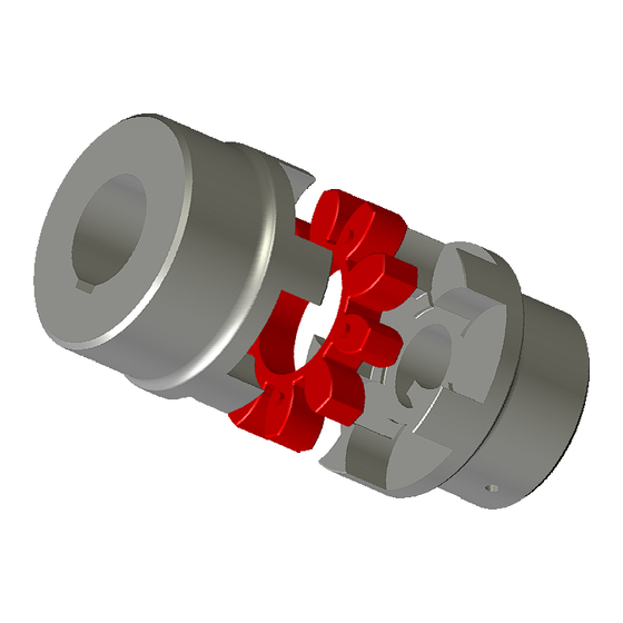
The milling of the seat of the flexible element of the GRMP guarantees a perfect coupling with the elastic spider in order to ensure a long life in the correct operating conditions. Mozzo Mozzo “B” “A” 114.01 - Rev. 3 - 24 April 2019 Approved by SIT S.p.A. -
Page 7: Table 2.2 Dimensions Trasco ® Grmp
L (B+B) L (AL+AL) L (BL+BL) 19/24 24/32 28/38 38/45 42/55 48/60 55/70 65/75 75/90 90/100 100/110 110/125 125/145 140/160 160/185 180/200 Table 2.3 - * dimensions in mm 114.01 - Rev. 3 - 24 April 2019 Approved by SIT S.p.A. -
Page 8: Grmalu Series Hubs
The TRASCO ® GRB series couplings for taper bush combines high performance characteristics, typical of standard hub coupling, the ease of use, assembly and disassembly, resulting from the coupling with a SER-SIT taper bush. (TABLE 2.5 - TRASCO GRB dimen- ®... -
Page 9: Table 2.5 Dimensions Trasco ® Grb
1 1/2-1 5/8-1 3/4-1 7/8-2-2 1/8-2 1/4-2 3/8-2 1/2-2 5/8-2 3/4-2 7/8-3-3 1/8-3 1/4-3 3/8-3 1/2 Table 2.5 * dimensions in mm ** Transmittable friction torque without the keyway 114.01 - Rev. 3 - 24 April 2019 Approved by SIT S.p.A. -
Page 10: Grs Series Hubs
48/60 13-48 13-60 1,36 1°30’ GRMP...B 55/70 16-55 16-70 1,52 1°30’ 65/75 16-65 16-75 1,75 1°30’ 75/90 16-75 16-90 1°30’ 90/100 21-90 21-100 1°30’ * dimensions in mm 114.01 - Rev. 3 - 24 April 2019 Approved by SIT S.p.A. -
Page 11: Grf Series Hubs
® GRMP...A GRMP...A GRMP...A Table 2.7 - Dimensioni TRASCO ® SIZE screws 19/24 40/32 24/32 55/40 28/32 65/48 38/45 42/55 48/60 55/70 65/75 75/90 90/100 100/110 110/125 125/145 114.01 - Rev. 3 - 24 April 2019 Approved by SIT S.p.A. -
Page 12: Table 2.8 Dimensions Trasco ® Grf
Figure 2-5 - GRF C Hubs GRMP...A GRMP...A Table 2.8 - Dimensioni TRASCO ® GRMP...A SIZE screws 19/24 40/32 24/32 55/40 28/32 65/48 38/45 42/55 48/60 55/70 65/75 75/90 90/100 100/110 110/125 125/145 114.01 - Rev. 3 - 24 April 2019 Approved by SIT S.p.A. -
Page 13: Hubs Machining
It is important not to exceed, for all the materials of which the hub is composed, the maximum value of the hole provided by SIT and reported in the technical catalogue; if this value is not respected the coupling may break, causing serious dangers during the rotation. -
Page 14: Position And Size Of The Setscrew
- Operating and Maintenance Manual ® 2.1.7 Position and size of the setscrew SIT supplies flathead setscrews class 45H according to DIN 913 for fastening the hub on the shaft. For the position and size of the setscrews, refer to TABLE 2.9 - TRASCO ®... -
Page 15: Elastic Spider
The standard version, is available, as standard product, in three hardness to suit different applications: • yellow ring 92 Sh A • red ring 98 Sh A • green ring 64 Sh D 114.01 - Rev. 3 - 24 April 2019 Approved by SIT S.p.A. -
Page 16: Elastic Spider Performance
95 Sh A 28000 56000 7280 1400 Note: For GRB and GRCAL types it is necessary to check the transmissible torque capacity, respectively, as from the bush and clamp 114.01 - Rev. 3 - 24 April 2019 Approved by SIT S.p.A. -
Page 17: Coupling Misalignments
It is important that the storage areas are protected against light sources, ultraviolet lamps, mercury vapour and high electrical voltage sources. The moisture percentage must be maintained below 65%. In good storage conditions the characteristics of the spiders can remain unchanged for up to 6 years. 114.01 - Rev. 3 - 24 April 2019 Approved by SIT S.p.A. -
Page 18: Assembling
The size of the spider is printed on a flat surface. ATTENTION! Install the hubs using only with the spider provided by SIT S.p.A. and of the same size. SIT S.p.A. assumes no liability for malfunctions and/or failures due to in- correct assembly or that does not comply with the instructions provided in this manual. -
Page 19: Table 4.1 Quote M
CAUTION! If the dimensions of shaft and key is lower than the diameter of the spider hole, one or both shafts may protrude into the spider. 114.01 - Rev. 3 - 24 April 2019 Approved by SIT S.p.A. -
Page 20: Grb Coupling Assembling
• 1 spider • 2 bushes • setscrews Figure 4-3 - Types of GRB The taper bush SER-SIT is a clamping device with threaded holes. ® Only half of the holes are in the bush, the other half are in the hub. -
Page 21: Taper Bush Disassembling
Figure 4-4 - GRS intermediate element Follow the instructions of the GRMP type making sure to check the value M (see - M Value) for both spiders. TABLE 4.1 114.01 - Rev. 3 - 24 April 2019 Approved by SIT S.p.A. -
Page 22: Grf Coupling Assembling
[Nm] [mm] 19/24 72° 24/32 72° 28/38 60° 38/45 60° 42/55 60° 48/60 45° 55/70 45° 65/75 36° 75/90 36° 90/100 30° 100/110 30° 110/125 30° 125/145 22°30’ 114.01 - Rev. 3 - 24 April 2019 Approved by SIT S.p.A. -
Page 23: Shaft-Flange Version
• Place the spider on one of the 2 flanges • Check the driving and driven hub to achieve the value M according to - M Value TABLE 4.1 114.01 - Rev. 3 - 24 April 2019 Approved by SIT S.p.A. -
Page 24: Shaft-Shaft Version
• join together the 2 flanges (CF/CFN) and the spider, then position the assembly between the flanged hubs • tighten the parts by hand GRF Screws • tighten the screws with a torque wrench as shown in the TABLE 4.3 114.01 - Rev. 3 - 24 April 2019 Approved by SIT S.p.A. -
Page 25: Atex Annex
- Operating and Maintenance Manual ® ATEX Annex This Annex is an integral part of the sale of the SIT TRASCO coupling according to the ATEX Directive 2014/34/EU, contains the De- ® claration of Conformity, and, therefore, is delivered together with the coupling. -
Page 26: Atex Equipment Classification
ATEX zones ® The analysis carried out by SIT S.p.A. led to the conclusion that the couplings can be used in the presence of flammable gases, va- pours, mists or combustible dusts according to the following scheme: • Gases, vapours or mists in zones 1 and 2 (not suitable for zone 0) •... -
Page 27: Marking
Directive ATEX 2014/34/EU for equipment operating in zones classified for the ® presen-ce of a potential hazardous atmosphere. The marking is indelible and positioned, at SIT’s discretion, in a suitable area of the hub surface. 5.4.1 Complete marking II 2G c IIC T6/T5/T4/T3 -30°<Ta<65°/80°/115°/120°C... -
Page 28: Hub Machining In Atex Environment
UNI-ISO 2768 standard. Any other machining on couplings to be used in hazardous zones must obtain the express consent of SIT. The customer must provide SIT with a technical drawing showing the machining to be carried out. It is the responsibility of SIT to evaluate and approve it. -
Page 29: Internal Manufacturing Check
• it is not subjected to the normal maintenance plans provided from the user and maintenance manual • it is not used as provided in the design specifications Different or additional uses not included in the technical specification are not permitted and SIT shall not be liable for any damage related to unauthorised uses. -
Page 30: Protection Devices For Couplings In Hazardous Atmospheres
The electrical resistance, measured between the various metallic parts of the coupling and the point of reference, must be verified at the time of initial installation and, subsequently, during periodic checks. 114.01 - Rev. 3 - 24 April 2019 Approved by SIT S.p.A. -
Page 31: Declaration Of Conformity
EN 13463-1 :2009 EN 13463-5 :2011 The technical documentation is filed with DNV GL AS P.O.Box 300 Veristasveien 1 1322 HOVIK Norway SIT S.p.A. Riccardo Scaglia Cusago, 24/05/2016 Managing Director 114.01 - Rev. 3 - 24 April 2019 Approved by SIT S.p.A.
Need help?
Do you have a question about the TRASCO GRMP Series and is the answer not in the manual?
Questions and answers