
Related Manuals for BERNSTEIN VDC-41-MT


Summary of Contents for BERNSTEIN VDC-41-MT
- Page 1 STACJA ZEWNĘTRZNA WIDEODOMOFONU VIDEO DOORPHONE VDC-41-MT Instrukcja obsługi User Manual...
- Page 3 ........5 ........ 11...
-
Page 5: Uwagi Wstępne
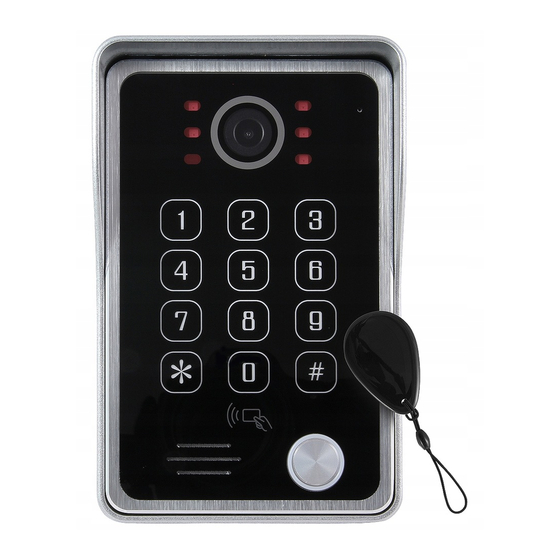
UWAGI WSTĘPNE Przed montażem, podłączeniem i użytkowaniem urządzenia prosimy o dokładne zapo- znanie się z niniejszą instrukcją obsługi. W razie jakichkolwiek problemów ze zrozumie- niem jej treści prosimy o skontaktowanie się ze sprzedawcą urządzenia. Samodzielny montaż i uruchomienie urządzenia jest możliwe pod warunkiem używania odpowiednich narzędzi. - Page 6 OPIS WYJŚĆ Ustawienie czasu zwalniania Głośność elektrozaczepu dla przycisku wyjścia (2S-10S) Zasilanie 12V * Gniazdo Przycisk wyjścia monitora Wyjście nieaktywne Dioda statusu urządzenia Dioda baterii Przycisk SET * Przy odległości instalacji przekraczającej około 30 m, należy zasilić kasetę zewnętrzną z zasilacza 12VDC min.1A. INSTALACJA STACJI ZEWNĘTRZNEJ...
-
Page 7: Schemat Połączeń
50 cm 50 cm Sposób montażu: 1. Odkręcić dolną śrubę mocującą i oddzielić stację od daszka ochronnego. 2. Poprzez 4 otwory w daszku ochronnym odznaczyć na ścianie miejsca na kołki montażowe. 3. W zaznaczonych miejscach nawiercić 4 otwory montażowe Ø6mm, a następnie umieścić... - Page 8 Przywracanie ustawień fabrycznych W trybie gotowości wciśnij przycisk SET na tylnej części obudowy na 3 sekundy aż usły- szysz dźwięk (di. .. ). Następnie wciśnij 3 razy przycisk SET. Trzy długie dźwięki (di. .. di. .. di. .. ) potwierdzają przywrócenie ustawień fabrycznych. Kod adminitstratora został...
- Page 9 Usuwanie karty (metoda 1) • wejdź w tryb programowania • wybierz 4 #, usłyszysz długi dźwięk (dii .. ), przycisk wywołania zacznie szybciej migać • wprowadź 3 cyfrowy numer użytkownika z zakresu od 000 do 199 i wybierz #, następ- nie ponownie wporwadź...
-
Page 10: Karta Gwarancyjna
KARTA GWARANCYJNA nazwa wyrobu: VDC-41-MT model: pieczątka punktu sprzedaży i podpis sprzedawcy data sprzedaży ........... OGÓLNE WARUNKI NAPRAW GWARANCYJNYCH 1. Eura-Tech Sp. z o. o. z siedzibą w Wejherowie przy ul. Przemysłowej 35A (zwany dalej „Gwarantem”), gwarantuje sprawne działanie wskazanego w Gwarancji urządzenia (zwanego dalej „Produktem”). - Page 11 INITIAL REMARKS Before assembling, wiring and setting up of device the user should carefully read given manual. In case of any troubles with understanding the content the user should contact the producer. Unassisted assembling and start of the device can be done only with the use of proper tools.
-
Page 12: Door Station Mounting
OUTPUTS DESCRIPTION Exit Button Unlock Time SPK (VOL) (2S-10S) Power 12V DC * Indoor Exit Button monitor Output inactive Status LED Battery LED indication * When installation distance is over 30 m is necessary to add external 12VDC power supply, min.1A DOOR STATION MOUNTING... -
Page 13: Wiring Diagram
50 cm 50 cm Mounting method: 1. Undo the lower fastening screw and separate the cassette from the protective roof. 2. Mark the places for the mounting pins on the wall, through the 4 holes in the protective roof. 3. Drill 4 mounting holes Ø6mm in the marked places, and then put 3 mounting pins inside them. - Page 14 Restore factory settings In standby mode, press the SET button on the back of the housing for 3 seconds until you hear sound (di ...). Then press the SET button 3 times. Three long beeps (di ... di ... di ...) confirm the restoration of factory settings. Admin code has been restored to 123456.
-
Page 15: Warranty
Removing a card (method 2) • enter the programming mode • select 4 #, you will hear a long beep (dii ..), the call button will flash faster • put the card close to the reader, a long beep (dii ...) confirms deletion. To delete another apply cards one after the other after a long beep (dii ..). - Page 16 Eura-Tech Sp. z o.o. ul. Przemysłowa 35A 84-200 Wejherowo Poland www.eura-tech.eu Wszystkie prawa zastrzeżone. Zdjęcia, rysunki i teksty użyte w niniejszej instrukcji obsługi są własnością firmy „EURA-TECH” Sp. z o.o. Powielanie, rozpowszechnianie i publikacja całości jak i fragmentów instrukcji są bez zgody autora zabronione! All rights reserved.
Need help?
Do you have a question about the VDC-41-MT and is the answer not in the manual?
Questions and answers