Table of Contents
Advertisement
Quick Links
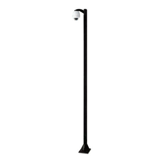
P1600
16' Video Surveillance Rated Fixed Steel CCTV Standard Pole Lowering Device
P1600....................... Standard 16' steel pole (4" x 4" tubing) with access panels on top and bottom, square base with a maximum load of 75 Lbs.
© 2013, Moog Inc. All Rights Reserved
Moog Inc.
Sensor and Surveillance Systems
3650 Woodhead Drive Northbrook, IL. USA 60062
+1.847.498.0700 Fax: +1.847.498.1258 www.moogS3.com
Installation and Operation Instructions
Before attempting to connect or operate this product, please
read these instructions completely.
81-IN5229 111813
Advertisement
Table of Contents

Related Manuals for Moog P1600

Summary of Contents for Moog P1600
- Page 1 P1600 16' Video Surveillance Rated Fixed Steel CCTV Standard Pole Lowering Device P1600....... Standard 16’ steel pole (4” x 4” tubing) with access panels on top and bottom, square base with a maximum load of 75 Lbs. Moog Inc. Sensor and Surveillance Systems 3650 Woodhead Drive Northbrook, IL.
-
Page 2: Important Safeguards
IMPORTANT SAFEGUARDS SAFETY PRECAUTIONS Read these instructions. Keep these instructions. CAUTION Heed all warnings RISK OF ELECTRIC SHOCK DO NOT OPEN Follow all instructions. Do not use this apparatus near water. CAUTION: TO REDUCE THE RISK OF Clean only with damp cloth. ELECTRIC SHOCK, DO NOT REMOVE COVER ( OR BACK). -
Page 3: Product Warranty Registration
Register Your Products Online www.moogS3.com/technical-support/product-registration Moog values your patronage. We are solely committed to providing you with the highest quality products and superior customer service. With 3-Year and 5-Year warranties (depending on the product purchased) we stand behind every product we sell. - Page 4 ™ During the labor warranty period, to repair the Product, Purchaser will either return the defective product, freight prepaid, or deliver it to Manufacturer at Moog Decatur Operations, 2525 Park Central Boulevard, Decatur, Georgia, 30035. The Product to be repaired is to be returned in either its original carton or a similar package affording an equal degree of protection with a RMA # (Return Materials Authorization number) displayed on the outer box or packing slip.
- Page 5 Part 1: Site Preparation Part 1: Site Preparation Figure 1 1. Select a suitable site for the P1600 and prepare the pad site NOTE: Special attention must be paid to the size of using a hole 36" x 36" x 36" deep. The top of the concrete the wiring conduit and its location within the foundation should be flush with the ground.
-
Page 6: Part 1: Site Preparation
Part 1: Site Preparation Part 1: Site Preparation Figure 4 Figure 3 FOR ANCHOR BOLT INSTALLATIONS: Prepare the concrete per manufacturer's directions. Pour concrete per manufacrurer’s directions. See Figure 3 for dimensions The concrete must have a compressive strength of of the bolt pattern and suspend appropriate bolts in the concrete around 3000 psi, and must be fabricated following ACI318-89 the wiring conduit. - Page 7 Part 2: Installation Part 2: Installation Figure 7 Figure 8 5. Slowly lift the pole into the upright position, aligning the holes of the Base Plate with the Bolts in the concrete pad (Figure 7). 6. Secure the pole to the pad with fasteners (Figure 8). CAUTION: Pull all slack in the wiring as Lock Washer...
- Page 8 Jig Assembly Jig Assembly Figure 3 Figure 2 2. Place the short end of each Bolt into the outside holes of the 3. Turn the Anchor Jig over and place Single Straps over the Bolts Cross Strap. Place Hex Nuts onto each Bolt and fi nger tighten (Figure 3).
- Page 9 Jig Assembly Jig Assembly Figure 6 Figure 7 With Leveling Nuts 6. If, due to conditions or other requirements, leveling nuts are NOTE: The Flat Washers, Lock Washers , and remaining Hex Nuts needed, adjustments will have to be made to the Anchor Jig . will be used to fasten the pole to the Anchor Jig.
Need help?
Do you have a question about the P1600 and is the answer not in the manual?
Questions and answers