Table of Contents
Advertisement
Quick Links
Advertisement
Table of Contents

Related Manuals for RSI VIDEO TECHNOLOGIES XT610

Summary of Contents for RSI VIDEO TECHNOLOGIES XT610
- Page 1 Document #2000-XTIN COMPLETE SETUP AND PROGRAMMING MANUAL XT610/XTX610/XTO610 GPRS PANELS *A Videofied CMA601 / XMB611(June 2011) Alphanumeric Keypad or Frontel TMT2 is required for programming and maintenance* CMA601 XMB611 4455 White Bear Parkway White Bear Lake, MN 55110 877-206-5800...
-
Page 2: Table Of Contents
2011/11/10 Ed 1.5 Setup and Programming manual for XT series GPRS Table of Contents Page FCC Guidelines Basic Guidelines Introduction Initial Programming 6-14 Entering Badges and Access Codes Choosing Siren Options Testing to Central Station Disabling Monitoring Testing GPRS Level Testing Device RF Level Connecting a GPRS Antenna Arming Input Wiring Diagram... - Page 3 2011/11/10 Ed 1.5 Setup and Programming manual for XT series GPRS Regulatory Information for USA and Canada FCC Part 15.21 Changes or modifications made to this equipment not expressly approved by RSI Video Technologies may void the FCC authorization to operate this equipment. FCC Part 15.105 Class B This equipment has been tested and found to comply with the limits for a Class B digital device, pursuant to Part 15 of the FCC Rules.
-
Page 4: Fcc Guidelines
2011/11/10 Ed 1.5 Setup and Programming manual for XT series GPRS Basic Setup Guidelines for Installation and Programming SETUP AND PROGRAM 1) Obtain the account number, IP address, and port number from the Central Station. 2) Activate the SIM card and obtain the APN code, username, and password by calling your cellular provider. -
Page 5: Basic Guidelines
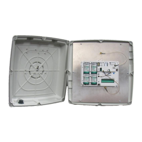
2011/11/10 Ed 1.5 Setup and Programming manual for XT series GPRS Introduction: Description: The XT series control panel is a Videofied wireless, battery operated hybrid alarm system. It is designed for residential, small business and commercial security applications. The XT provides integrated Video Verification over GPRS. - Page 6 2011/11/10 Ed 1.5 Setup and Programming manual for XT series GPRS SETUP MANUAL XT SERIES GPRS PANEL *THIS SYSTEM REQUIRES A CMA601/XMB611 or TMT INSTALLER SOFTWARE FOR PROGRAMMING* XT Initial Programming Open the Control Panel Using a #1 Phillips screwdriver, remove the 2 screws holding the cover on.
- Page 7 2011/11/10 Ed 1.5 Setup and Programming manual for XT series GPRS *The SIM card must NOT be inserted or removed while the panel is powered* Install the SIM card Slide SIM card into the slot. Make sure it is aligned correctly. Powering the Panel **THE CONTROL PANEL MUST BE CONNECTED TO AN EXTERAL POWER SUPPLY WHEN SMS FEATURE IS ACTIVE**...
- Page 8 2011/11/10 Ed 1.5 Setup and Programming manual for XT series GPRS WARNINGS: 1. DO NOT USE ALKALINE BATTERIES IF INSTALLING AN XTX/XTO GPRS BELOW 30° F, YOU MUST USE OPTION 1: PP1. 2. DO NOT INSTALL A TRANSFORMER WHEN USING OPTION 1 (LITHIUM BATTERIES).
- Page 9 2011/11/10 Ed 1.5 Setup and Programming manual for XT series GPRS XT Programming Reset the XT Panel: Press and hold programming button ( ) for 10sec until the Indicator LED blinks twice Press and instantly release the programming button ( The indicator LED will blink once.
-
Page 10: Initial Programming
2011/11/10 Ed 1.5 Setup and Programming manual for XT series GPRS RADIO RANGE The Radio Range test should be run during device TEST ? recording to ensure proper pairing with the control panel. This test is the communication strength between the device and the control panel. - Page 11 2011/11/10 Ed 1.5 Setup and Programming manual for XT series GPRS DATE (Day) : 09/06/01 DATE (Day) : Use the to set the Day 09/06/03 TIME (HOUR) : 00:00 TIME (HOUR) : to set the Hour – The system uses a Use the 10:00 24 hour clock.
- Page 12 2011/11/10 Ed 1.5 Setup and Programming manual for XT series GPRS CODE/STATE modification These are the default transmitted events: Device Alarm Alert Alarm Initialization Not Transmitted Panel Batteries Alarm/End CODE/STATE AC Power Alarm/End MODIFICATION ? Phoneline Fault Not Transmitted Tamper Alarm/End Device Batt.
- Page 13 2011/11/10 Ed 1.5 Setup and Programming manual for XT series GPRS Using the control panel as a Xtender system will only be able to arm and disarm by latching 9-12v to one of the two inputs. Arming input 1 will control the arming and disarming of devices in areas 1 and 2. Where devices in area 1 are subject to the Entry Delay.
- Page 14 2011/11/10 Ed 1.5 Setup and Programming manual for XT series GPRS GPRS PARAMETERS ? Your APN code (Access Point Name) is given to you by your APN CODE Cellular Provider. Press YES to enter into the parameter ...
- Page 15 2011/11/10 Ed 1.5 Setup and Programming manual for XT series GPRS GPRS LEVEL? During the GPRS Level test the Modem will boot and attempt to gain access to the internet to post a Level out of 5 or an error Code that will help troubleshoot why it cannot connect.
-
Page 16: Entering Badges And Access Codes
2011/11/10 Ed 1.5 Setup and Programming manual for XT series GPRS Entering a Badge or Access Code for Arming/Disarming After Initial programming has been completed, you are not able to arm and disarm the system until you enter a user code or badge (the installer code cannot arm and disarm the system). Codes can be 4-6 digits and the 4 digit must be 2 values higher or lower than any other code on the system: Example: User code 1234, next code cannot be 1235, 1236, 1233, or 1232 –... -
Page 17: Choosing Siren Options
2011/11/10 Ed 1.5 Setup and Programming manual for XT series GPRS Changing Siren Options After initial programming has been completed any sounder on the system will be enabled by default, this includes the sounder on the Keypad and Badge Reader. While there is no way to disable the sounding of the exit delay you are able to disable the intrusion sound. -
Page 18: Testing To Central Station
2011/11/10 Ed 1.5 Setup and Programming manual for XT series GPRS How to test to the dispatch center Testing to the dispatch is done twice during installation. Once while you are programming the system and then again once the installation has been completely finished. Although both will use the same steps the initial test will be just confirmation using one device to verify the programming. -
Page 19: Disabling Monitoring
2011/11/10 Ed 1.5 Setup and Programming manual for XT series GPRS How to Disable Monitoring Disabling monitoring can be a useful tool in many situations. Before mounting devices and moving the panel to find a good GPRS level, disabling monitoring will ensure that you will have access to programming and that unnecessary signals are not sent to the monitoring station. -
Page 20: Testing Gprs Level
2011/11/10 Ed 1.5 Setup and Programming manual for XT series GPRS How to test GPRS for deployment of panel Before the system is mounted you will need to check the GPRS level to make sure it is adequate. If the level is 3/5 or better you can mount the control panel in that location. -
Page 21: Testing Device Rf Level
2011/11/10 Ed 1.5 Setup and Programming manual for XT series GPRS How to test RF for deployment of devices Running the RF test during the mounting of devices is key to a successful Videofied installation. This test will ensure that all devices have adequate communication with the control panel. All Videofied devices are bi-directional which allows the system to ping the device and expect a response. -
Page 22: Connecting A Gprs Antenna
2011/11/10 Ed 1.5 Setup and Programming manual for XT series GPRS GPRS Antenna Connection ! WARNING ! Use caution before removing antenna connection. Damaged antenna connector is NOT covered under warranty. Using needle nose pliers, be sure to only grab the connector and pull directly up Arming Input Wiring Diagram HOST... -
Page 23: Programmable Input Configuration
2011/11/10 Ed 1.5 Setup and Programming manual for XT series GPRS General Programmable Input Configuration 23 | P a g e 4455 White Bear Parkway, Suite 700 White Bear Lake, MN 55110... - Page 24 2011/11/10 Ed 1.5 Setup and Programming manual for XT series GPRS 24 | P a g e 4455 White Bear Parkway, Suite 700 White Bear Lake, MN 55110...
- Page 25 2011/11/10 Ed 1.5 Setup and Programming manual for XT series GPRS 25 | P a g e 4455 White Bear Parkway, Suite 700 White Bear Lake, MN 55110...
-
Page 26: Programmable Output Configuration
2011/11/10 Ed 1.5 Setup and Programming manual for XT series GPRS 26 | P a g e 4455 White Bear Parkway, Suite 700 White Bear Lake, MN 55110... - Page 27 2011/11/10 Ed 1.5 Setup and Programming manual for XT series GPRS 27 | P a g e 4455 White Bear Parkway, Suite 700 White Bear Lake, MN 55110...
- Page 28 2011/11/10 Ed 1.5 Setup and Programming manual for XT series GPRS 28 | P a g e 4455 White Bear Parkway, Suite 700 White Bear Lake, MN 55110...
-
Page 29: Configuring Scheduling
2011/11/10 Ed 1.5 Setup and Programming manual for XT series GPRS 29 | P a g e 4455 White Bear Parkway, Suite 700 White Bear Lake, MN 55110... - Page 30 2011/11/10 Ed 1.5 Setup and Programming manual for XT series GPRS 30 | P a g e 4455 White Bear Parkway, Suite 700 White Bear Lake, MN 55110...
- Page 31 2011/11/10 Ed 1.5 Setup and Programming manual for XT series GPRS 31 | P a g e 4455 White Bear Parkway, Suite 700 White Bear Lake, MN 55110...
-
Page 32: Enabling External Rf Antenna
2011/11/10 Ed 1.5 Setup and Programming manual for XT series GPRS How to enable the External RF Antenna The XTO 600/610 control panels have built in High Gain RF and GPRS antennas. The GPRS external comes pre-activated and hooked up, while the RF antenna is hooked up but needs to be activated in Configuration after you have completed initial programming. -
Page 33: Mounting Xt/Xtx
2011/11/10 Ed 1.5 Setup and Programming manual for XT series GPRS How to mount the XT600i/610 and XTX600/610 How to Mount the Control Panel? Fix the back casing on the wall with 3 screws () How to Mount the XTO600/610 Included Mounting Hardware: Case and Mounting Mounting Brackets... - Page 34 2011/11/10 Ed 1.5 Setup and Programming manual for XT series GPRS 2. Place the cover on the base. 1. When closing the cover be sure to line up the two BOTTOM stickers face to face. 2. Be Careful not to slide the cover on.
-
Page 35: Troubleshooting
2011/11/10 Ed 1.5 Setup and Programming manual for XT series GPRS Troubleshooting Monitoring Station is not getting ANY video but is getting signals: Good communication between the MotionViewers and the Control Panel is key to getting successful video to the monitoring station. During mounting of any device on your Videofied system you must run the Radio Range/Device Locating test to ensure that the mounting location is with-in range of the Control Panel. -
Page 36: Central Station Not Getting Any Signals
2011/11/10 Ed 1.5 Setup and Programming manual for XT series GPRS Monitoring Station is not getting any signals: Communication between the Control Panel and the Monitoring Station is over the GPRS side of the GSM cellular network. You will want to check your GPRS level to see if there is an error/level is too low. You must have a 3/5 or better for reliable transmission to the Monitoring Station. -
Page 37: Unable To Record Device Or Getting 'Pairing Failure' Error
2011/11/10 Ed 1.5 Setup and Programming manual for XT series GPRS Unable to record device or getting ‘Pairing Failure’ error This usually occurs when the device still has a pairing key from a previous system or setup. To perform a pairing key override: 1. - Page 38 2011/11/10 Ed 1.5 Setup and Programming manual for XT series GPRS PROGRAMMABLE INPUTS CONFIGURATION Page 36 Page 37 Page 37 Page 38 Page 39 GENERAL ALARM MODES RESPONDING AREAS AND CONFIGURATION PARAMETERS PROGRAMMABLE PARTY LIST DEVICES MONITOR. STATION SITE VIDEOMAIL ALARM MONITORING FULLY ARMED DEVICES...
- Page 39 2011/11/10 Ed 1.5 Setup and Programming manual for XT series GPRS GENERAL PARAMETERS GENERAL PARAMETERS SITE GPRS IDENTIFICATION PARAMETERS PANEL PHONE NUMBER APN CODE NAME OR ADDRESS USERNAME XTENDER PASSWORD ARMING OPTION STANDALONE IP ADDRESS 1 0.0.0.0 ENTRY DELAY DOMAIN NAME 1 TRANSMISSION DELAY 000 PORT 1...
- Page 40 2011/11/10 Ed 1.5 Setup and Programming manual for XT series GPRS ALARM MODES PROGRAMMABLE / RESPONDING PARTY LIST ALARM MODES RESPONDING PROGRAMMABLE PARTY LIST VIDEOMAIL ALARM FULLY ARMED ADDRESS AREAS:1234 SELECT/MODIFY STATE: AAAA EMAIL ADDRESS ALARM: ENTER NEW EMAIL SIREN ADDRESS EMAIL SENDER ALARM MODE SP1...
- Page 41 2011/11/10 Ed 1.5 Setup and Programming manual for XT series GPRS AREAS AND DEVICES AREAS AND DEVICES EXIT DELAY DEVICES 45sec ADD A NEW DELAY BEEPS DEVICE ENABLED DEVICE AUTO ARMING CONFIGURATION DELAY DISABLED LIST OF DEVICES SCEDULING DELETE DEVICE SCHEDULING OFF CHANGING NAME CALENDAR...
- Page 42 2011/11/10 Ed 1.5 Setup and Programming manual for XT series GPRS CONFIGURATION MONITOR. STATION CONFIGURATION MONITOR. STATION MONITORING PARAMETERS MONITORING ENABLED ACCOUNT NUMBER PERIODIC TEST PERIODIC TEST 24 HOURS TEST HOUR 15:00 SYSTEM ARMED DISABLED ALARM CODES TRANS. STATE MODIFICATION LIST OF TRANSMITTED EVENTS...
-
Page 43: Addendum
2011/11/10 Ed 1.5 Setup and Programming manual for XT series GPRS Addendum 1. LSH20 Control Panel Batteries: 2. LS14500 Peripheral Batteries: Excludes SE601 and SE651 3. Lithium Battery Storage: 43 | P a g e 4455 White Bear Parkway, Suite 700 White Bear Lake, MN 55110... - Page 44 2011/11/10 Ed 1.5 Setup and Programming manual for XT series GPRS 4. Finding Manufacture Week and Year: The Manufacture week and year can be found in the serial number of the device/control panel. The second sets of 4 numbers in the serial number are WWYY. ####0411######## = Which shows that this device was manufactured in the 4 week of 2011.
Need help?
Do you have a question about the XT610 and is the answer not in the manual?
Questions and answers