Advertisement
Quick Links
8
Co-Pilot™ II specifi cations
Operating voltage
+3.5 to +9 volts DC
Operating current
<10 milliamps (servos may draw more current from rapid move-
ment and stabilization)
Weight
Computer: 0.61oz (19gm)
Main Sensor Module: 0.23oz (7gm)
Vertical Sensor Module: 0.16oz (5gm)
IRNet Router: 0.26oz (8gm)
Sensor fi eld of view
60° radius cone from window center line
Leveling response time
1/60th second
Drift from level
<2°
Flying conditions
Day and night; all weather conditions (rain, fog, sleet and snow
may degrade performance)
Humidity
Sensor is sealed; keep windows clean
Remote activation
On/off control and selection of Flight Modes
Aircraft types
Works with all aircraft confi gurations, including dual aileron ser-
vos, quad fl aps, elevons, V-tail, VTOL complex transmitter mixes,
digital servos and CCPM
FMA limited warranty
FMA, Inc. warrants this product to be free of manufacturing defects for the term of 1 year from the date of pur-
chase. Should any defects covered by this warranty occur, the product shall be repaired or replaced with a unit of
equal performance by FMA or an authorized FMA service station.
Limits and exclusions
This warranty may be enforced only by the original purchaser, who uses this product in its original condition as
purchased, in strict accordance with the product's instructions. Units returned for warranty service to an FMA
service center will be accepted for service when shipped postpaid, with a copy of the original sales receipt or war-
ranty registration form, to the service station designated by FMA.
This warranty does not apply to:
Consequential or incidental losses resulting from the use of this product.
Damage resulting from accident, misuse, abuse, neglect, electrical surges, reversed polarity on connectors,
lightning or other acts of God.
Damage from failure to follow instructions supplied with the product.
Damage occurring during shipment of the product either to the customer or from the customer for service
(claims must be presented to the carrier).
Damage resulting from repair, adjustment, or any alteration of the product by anyone other than an authorized
FMA technician.
Installation or removal charges, or damage caused by improper installation or removal.
Call (301) 668-4280 for more information about service and warranty repairs.
A detailed reference manual for this
product, including feature explanations
and fl ying tips, is available as a PDF at
www.fmadirect.com/downloads.htm
Installing Co-Pilot II
Parts list
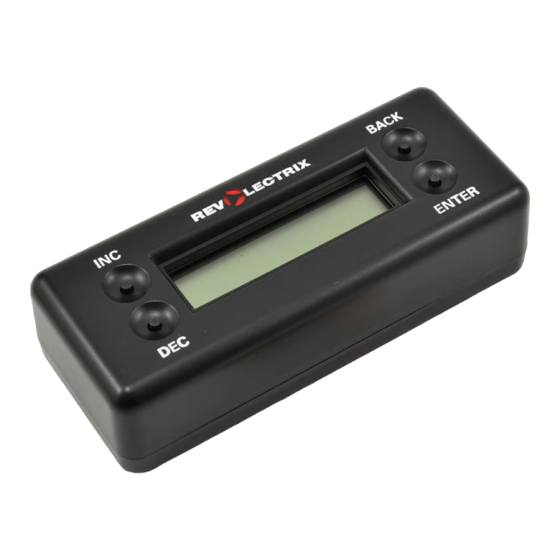
IRNet Programmer (Part no. IRNHP)
IRNet Router (Part no. IRNRTR)
Co-Pilot II Computer (Part No. CPII-CM)
Main Sensor Module (Part no. CPII-MS)
3 heli boom mounts
with double-sided adhesive
(Part no. CPIISENMOUNT)
5 1"x1" double-sided adhesive strips
(Part no. CPIITAPE)
6 6" nylon cable ties (Part no. NWT0.1x6)
Optional components
Vertical Sensor Module (Part no. CPII-ZS)
USB Interface Module (Part no. FUIM2 or FUIM3)
Other items you may need
3 AAA batteries (to power IRNet Programmer)
Servo extension cables
Installing batteries in the Programmer
1. Remove four screws securing the back of the Programmer.
2. Insert three AAA batteries.
3. Replace the back of the Programmer and secure with four screws.
Before you start: Flight stabilization works with—and requires—a completely installed and cor-
rectly operating aircraft radio control system: transmitter, battery pack and servos. Install and set
up your entire radio system before you connect Co-Pilot II to it. Be absolutely certain the radio
system operates correctly and moves the control surfaces in the proper directions. Once the radio
system is working correctly, then install and confi gure the Co-Pilot II system.
Co-Pilot is a trademark of FMA, Inc. U.S. Patent 6,181,989. Patents held in Germany and UK. Patents pending elsewhere.
FMA, Inc.
5713 Industry Lane, Suite 50
Frederick, MD 21704
Sales: (800) 343-2934
090728
Co-Pilot II Quick Start
Condensed instructions for installing and
programming the Co-Pilot™ II Advanced Infrared
Flight Stabilization System
Technical: (301) 668-4280
www.fmadirect.com
Advertisement

Summary of Contents for FMA REVOLECTRIX Co-Pilot II
- Page 1 2. Insert three AAA batteries. FMA, Inc. warrants this product to be free of manufacturing defects for the term of 1 year from the date of pur- chase. Should any defects covered by this warranty occur, the product shall be repaired or replaced with a unit of 3.
- Page 2 Use double-sided adhesive strips (included) or hook-and-loop fasteners (not included) to se- 2. Launch the updater: Start > Programs > FMA Direct > Co-Pilot II Update. cure Module to wing or fuselage. Use the special heli mounts (included) to secure the Sensor to a helicopter boom (boom mounting details below).
- Page 3 Module to the plastic mount. The Sensor Module should be rotated 45° relative to the Vx.x FMA Inc. boom. Sensors 2 and 3 will face forward so 2. Turn on the Co-Pilot II Computer (by turning on the aircraft receiver).
- Page 4 Mounting on an airplane If helicopter channels are limited The Vertical Sensor Module is typically mounted As initially confi gured, many CCPM helicopter radio systems don’t have a free channel for turn- on the side of the fuselage. ing Co-Pilot II on/off and selecting Flight Modes. If your helicopter doesn’t use four channels for fl...


Need help?
Do you have a question about the REVOLECTRIX Co-Pilot II and is the answer not in the manual?
Questions and answers