Table of Contents
Advertisement
Quick Links
NEW, IMPROVED!
NOW CONTAINS CARBON
FIBER SPAR!
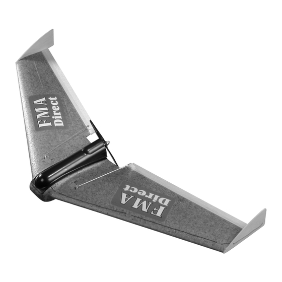
RAZOR Flying Wing Almost Ready-To-Fly R/C Airplane
ASSEMBLY AND OPERATIONS MANUAL FOR PARK RAZOR, 400 AND 600 CLASS KITS AND
RTF MODELS - PARK RAZOR ASSEMBLY ALSO REQUIRES PARK RAZOR ADDENDUM - PARK
NOTE: PLEASE READ MANUAL COMPLETELY BEFORE OPERATION
FMA, Inc.
5716A Industry Lane
Frederick, MD 21704
Sales: (800) 343-2934 -Technical: (301) 668-7614
www.fmadirect.com
RAZOR DOES NOT CONTAIN CARBON FIBER SPAR
Manual Release V 2.0
1
Advertisement
Table of Contents

Related Manuals for FMA RAZOR


Summary of Contents for FMA RAZOR
- Page 1 FIBER SPAR! RAZOR Flying Wing Almost Ready-To-Fly R/C Airplane ASSEMBLY AND OPERATIONS MANUAL FOR PARK RAZOR, 400 AND 600 CLASS KITS AND RTF MODELS - PARK RAZOR ASSEMBLY ALSO REQUIRES PARK RAZOR ADDENDUM - PARK RAZOR DOES NOT CONTAIN CARBON FIBER SPAR NOTE: PLEASE READ MANUAL COMPLETELY BEFORE OPERATION FMA, Inc.
-
Page 2: Specifications
Extensive flight testing by FMA engineers has demonstrated the incredible shock absorption and impact resistance of RAZOR by spinning the airplane in from as high as 100 feet directly on the nose with little or no damage to the basic wing structure. With the addition of a 22” carbon fiber spar in- cluded in the kits, RAZOR is arguably the most durable R/C aircraft available today. -
Page 3: Safety Precautions
PACKAGE CONTENTS Carefully unpack the contents of your RAZOR kit and lay the parts out on a clean workspace, ready for assembly. Identify your kit and verify that it contains the items listed in the following table. Note: if you discover that something is missing or damaged, please contact the authorized FMA Direct dealer where you purchased the product or phone FMA Direct at (301) 668-7614. - Page 4 ASSEMBLY INSTRUCTIONS Proceed carefully through each of the following assembly steps. Please read each step completely before you begin that step. If you are uncertain about the instructions provided, please call FMA Direct technical assistance at (301) 831-8980. STEP 1: ARCEL (TM) foam contains polyethylene.
- Page 5 ARCEL (TM) STEP 5: The new improved RAZOR kits and ARF’s now come with a pre-cut, 22” long, 5.5mm diameter carbon fiber arrow shaft. The shaft has been incorporated into the model as a wing spar to further en- hance wing strength during high powered aerobatics and the occa- sional but often unavoidable crash.
- Page 6 Mist on one or two fine coats of pigment. Use only enough paint to add color. Too much paint and you will add excess weight and possibly warp the foam wings. If you intend to paint your RAZOR, be sure to...
- Page 7 STEP 10: If you have a 600 class kit, apply the 0.010” x 20” tape you prepared in STEP 9 to the aircraft as illustrated. Please note, the tape shown in this photo is only for positioning. You will need to remove the adhesive backing before installing the tape.
- Page 8 STEP 14: Trim the back face of the canopy out to allow the motor and prop assembly to protrude from the back of the airframe. Cut to within 1/8” of the edge so that the part remains strong. Do not cut on the edge or the part will be too flimsy and may tear over time.
- Page 9 STEP 18: Locate one of the two pieces of 0.005” (thin) LEXAN (TM) tape. Mark the tape at 2 3/4”. This small piece of tape will be used to hinge the canopy to the equipment tray for easy access to flight pack and propulsion equipment.
- Page 10 STEP 24: The motor pack that shipped with your ARF is made up of the ESC, the motor, capacitors, Shottky barrier diode, and wiring, pre- assembled and ready for installation. If you are not using an FMA Direct motor pack, please refer to the diagram following this step for proper connection of ESC / motor.
- Page 11 STEP 25: Assemble the motor pack to the equipment tray as illustrated. Feed the nylon tie through the holes you cut in the motor mount. Pull the nylon tie tight so that the clamp is resting closest to either hole and cut off the excess. STEP 26: Locate two pieces of the 0.010”...
- Page 12 STEP 29: This illustration shows the placement of the structural and servo tapes prepared in STEP 26 for a 600 class kit. Do not install the tapes at this time, but test the placement of each as follows. The long tape should be positioned so that the end closest to the fuselage begins where the wing joins the fuselage and is centered over the servo wire slot.
-
Page 13: Black Wire
STEP 33: Turn the airframe upside down and hang the fuselage and one wing half over the edge of the table as illustrated. Remove the backing from the tape and place the tape on the bottom of the wing as detailed in the previous steps. Make certain the wing is flat on the table top so no warping of the wing can occur. - Page 14 STEP 37: Open the canopy. Connect the two servo leads to the receiver outputs. Connect the ESC lead to the receiver. Don’t worry if you are not sure which channels are the correct ones for now, you will double check this in final installation. Using double-sided foam tape (not supplied), tape down the ESC, power switch and receiver as illustrated.
- Page 15 TIP: It is always a good idea to cover your elevon and winglet surfaces with covering material before installation to prevent moisture from getting into the wood and causing warping or adding weight. STEP 41: Locate the two strips of 0.005” (thin) LEXAN tape.
- Page 16 STEP 45: Using a small bit that is slightly smaller than the outside diameter of the pushrods, open up the second hole down on the servo arms to accept the pushrods. The fit should be tight to prevent any slop in the linkages. STEP 46: Make sure the ESC power switch is off.
- Page 17 STEP 49: Screw the clevis onto the pushrods. Install the pushrods to the servo output arms from the out-board side of the servo. Your kit contains one left and one right pushrod. Before snapping the clevis to the control horn, adjust the length of the rod so that when the pushrods are installed, the elevons are set for 2 degrees up elevon.
- Page 18 If you are new to radio control, it is important that you seek the help of an experienced modeler to help you set up and learn to fly your new RAZOR. The hardest part of learning to fly is adjusting the control surfaces and “trimming” out the model during the initial flights.
-
Page 19: Quick Review
“yaw” which changes the direction of the tail relative to the nose of the aircraft. All turns with RAZOR will be performed by banking the airplane left or right as opposed to creating yaw. -
Page 20: Spare Parts
CONVERTING AIRPLANE MODELS If you purchased the slope soar model of the RAZOR, and later wish to convert it over to a 400 Class model, purchase a 400 motor pack and a 7 cell 600AE battery. Follow the instructions in this manual for installation. If you purchased the 600 Class “Endurance”...
Need help?
Do you have a question about the RAZOR and is the answer not in the manual?
Questions and answers