
Subscribe to Our Youtube Channel
Summary of Contents for Digitus DN-97332
- Page 1 Split Rack Cooling Unit User Manual DN-97332 (3.9 kW) DN-97333 (7.2 kW) DN-97334 (12 kW)
-
Page 2: Table Of Contents
Table of Contents 1. Security Information ................... 3 1.1. Symbol Description ................3 1.2. Handle Information ................4 2. General Information ................... 6 2.1. Product Identification ................. 6 2.2. Size ...................... 8 2.3. Envrionmental Requirements ............. 9 3. Installation ....................9 3.1. -
Page 3: Security Information
1. Security Information 1.1. Symbol Description Installation, operation, or maintenance of equipment before servicing, please read the manual carefully and keep in mind. Other matters on the information in this manual or equipment, the following symbols illustrate messages may appear to warn of potential danger or attention. Add this symbol indicates that fails to comply with the instructions;... -
Page 4: Handle Information
NOTICE NOTICE addresses practices not related to physical injury including certain environmental hazards, potential damage or loss of data. 1.2. Handle Information Read the handle information before trying to install, operate, service, or maintain it. Comply with local regulation and law when handle refrigerant. - Page 5 CAUTION Hazard to equipment or personnel • All work must be performed by qualified personnel. Or it can result in serious injury or equipment damage. CAUTION Hazard of equipment falling over • Use two or more persons at all times to move or turn this equipment. •...
-
Page 6: General Information
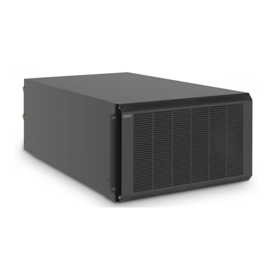
2. General Information 2.1. Product Identification FIG 2-1 3.9 kW/7.2 kW/12 kW exterior view (left side is a front view, right side is a rear view) 1. Shut off valve 2. The front panel 3. Breaker The compressor - the main role of the refrigeration system through the evaporator for evaporating low pressure refrigerant gas compressed at room temperature to a temperature high-pressure refrigerant gas, increasing its temperature of condensation, into the condenser (outdoor unit) is... - Page 7 Shut-off valve - off device for manual flow conduit connecting pipe (connecting indoor and outdoor) in the refrigerant. Filter drier - protection refrigeration systems, water filtration systems, solid acid and impurities. The expansion valve - electronic expansion valve, the refrigerant flow rate regulator.
-
Page 8: Size
1. Connection port 2. Shut off valve 3. Mounting feet 2.2. Size Table 2-1 Indoor unit size Product number Width (mm) Depth (mm) Height (mm) DN-97332 DN-97333 DN-97334 Table 2-2 Outdoor unit size Product number Width (mm) Depth (mm) Height (mm) DN-97332... -
Page 9: Envrionmental Requirements
2.3. Envrionmental Requirements Operating Envrionment Table 2-3 Products Operating Environment Project Indoor side Outside the room Temperature 18 °C ~ 40 °C Air cooled: -20 °C ~ +45 °C Humidity 20 % to 80 % Altitude <1 000 m Altitude Greater than 1 000 m Derating about 6 % / one thousand meters 220 ~ 240 V single-phase or three-phase 380 ~ 415 V... - Page 10 Material preparation Brass. Pipe support member, drain line, a power cable. Even if the air conditioning is a long tube, you need the additional material. Brass, cotton insulation of R410A refrigerant, refrigerant oil (also at low temperatures when filling component). Site Preparation Indoor: installation location out of the device should be easy, the ground should be able to carry the weight of the carrier device, installation location...
- Page 11 2. If positive gap is bigger than 20 m or connecting pipe is longer than 30 m. Extension component is needed. 3. Install oil bending in every 6 m vertical height of gas pipe when the installation vertical height is over 10 m. 4.
-
Page 12: Unpacking Inspection
If so, then the needle cap to re-install the good. 3.3. Installation 3.3.1. Outdoor Installation Installation DN-97332/DN-97333/DN-97334 1. The outdoor unit placed on the base. 2. The outdoor unit expansion bolts fixed to the base. Piping Installation Piping principle 1. - Page 13 30 m Model ØD ØL ØD ØL ØD ØL (mm) (mm) (mm) (mm) (mm) (mm) DN-97332 DN-97333 DN-97334 Table 3-3 Equivalent length of the sub-assembly Fluid tube Equivalent length (m) diameter (mm) Elbow 90° Elbow 45° T-piece 0.21 0.10 0.76 0.24 0.12...
- Page 14 operation, the operation of a spanner easily because damage to the copper tube connected to the valve. Note refrigerant line connected to 1. Manufacturers provide 3.9 kW/7.2 kW/12 kW 5 m standard pipe, such as pipes require a longer, contact with the sales staff. 2.
-
Page 15: Indoor Installation
3.3.2. Indoor Installation Mechanical Installation Install rack mounted cooling unit in the rack. Sewer Installation Drain pipe is 20mm, drainage pipes and fittings with the room air conditioning drain access the drainage system. 1. The drain is not directly exposed to the temperature is below 0 ℃. When installing sewer, note the following requirements: 2. -
Page 16: Commissioning
4. The power supply circuit breaker and fuse rating to meet the needs of the unit. 5. If the monitoring cable, check the monitor cable is connected. 6. Check all cables, connectors have been tightened, without loosening the fixing screws. 4. -
Page 17: Add The Amount Of Lubricating Oil
The addition amount of the refrigerant can be calculated according to the following formula: The addition amount of the refrigerant (kg) = Control unit length was added in an amount of refrigerant (kg / m) × the total length of the liquid extension pipe (m) 3.9 kW/7.2 kW/12 kW extend the overall length was set (m) = Total length of catheter -5m (m);... -
Page 18: Boot Check
Table 4-2 Air conditioning allows maximum charge amount Model The maximum allowed amount of charge – kg DN-97332 DN-97333 DN-97334 Note: SmoothAir precision air conditioning uses R410A environmentally friendly refrigerant compressor lubricants in strict accordance provide models to buy. The refrigerant R410A be added RL68H (or the other makes the same viscosity) synthetic oils. -
Page 19: Run The Debugger
of pipelines; oil unbending installed in the correct position Heater Securely mounted electric heater Humidifier To the sewer connection in place, the wiring is correct. If no configuration is ignored. After checking the above items before power supply to the unit operation. -
Page 20: Debugging Content
4.4.2. Debugging Content a) Measuring and recording operating parameters of the unit (return air temperature, air temperature, the liquid pipe pressure, intake pressure, temperature of the valve before the intake air temperature); b) Adjusting the operating parameters of the compressor (the compressor suction, discharge pressure control in a suitable range, and adjust the degree of superheat and subcooling to a suitable value);... -
Page 21: Common Fault Alarm Phenomenon And Measures
Suction pressure and discharge pressure is normal Confirmed that the amount of refrigerant charge is appropriate Whether the refrigerant leakage phenomenon See color sight glass Cooling Drain water tray is smooth System If there is frost expansion valve Whether the compressor frost occurs Whether evaporator frost occurs Line for damage Pipe insulation is normal... - Page 22 Excessive Excess refrigerant discharged refrigerant system within the system Compressor axle, the motor coil Compressor own insulation in question must be fault replaced compressor Supply Voltage Negative power supply voltage Value instability factor Compressor loose Good re-tighten the compressor wiring terminal Pressure Replace the pressure protection...
- Page 23 Voltage is too low Check input power Fan motor winding Check whether the motor fault windings normal Low Voltage Replace the low protection Protection Switch switch Fault Appropriately adjusting the Expansion valve is opening degree of the expansion too small valve The expansion An expansion valve replacement,...
- Page 24 Refrigeration system is not Check the cooling system work turned on Temperature limit Reset temperature is unreasonable alarm Winter examination room sealed Site irregularities situation, the venue for unusual circumstances No high-humidity Increased thermal load heat load Humidity limit set Reset humidity unreasonable...
-
Page 25: Control System
6. Control System 6.1. Interface Description The program interface is divided into homepage, menu page, and alarm page. Figure 6-1 Home Automatically enter the home page when you are on power. Or automatically return to the home page if the interface is not operated for a long time. (21:10/2018-03-24) Time/date: show current date, You can change the time in the clock Settings. - Page 26 (Censored) When there is an alarm, there will be a warning sound, click the noise to eliminate the alarm sound. (Operating state refrigeration and heat dehumidification humidifier) various functional operation status. Menu Figure 6-2 Menu You can enter the menu page at other page point menu. (I/O) Click to enter the input output page, including all digital input output information and analog quantity input and output information.
- Page 27 Alarm Figure 6-3 Current alarm Under this menu, you can view all alarms that exist in the current unit. (Trigger date) the exact date of the alarm. (Trigger time) The timing of the alarm. (Alarm content) Warning. (Return) The return key is returned to the previous page. (Next page) Page turn option, click to enter the history alarm page.
- Page 28 Figure 6-4 History alarm Under this menu, you can view all the uncleared alarms that have occurred before the current crew. (serial number) Alarm number. (date) The exact date of the alarm. (time) The timing of the alarm. (alarm content) Alarm content. (return) The return key is returned to the previous page.
- Page 29 Input/Output 1 Figure 6-5 Input/output1 Under this menu, you can view the current unit number input state and digital output status. When the output status of the device is blue, the device is in the output state and the device is in a non-output state when the color is gray.
- Page 30 Input/Output 2 Figure 6-6 Input/output1 Under this menu, you can view the current unit simulation input and output values. (temperature and humidity curve) Click to enter the temperature and humidity curve interface. (pressure curve) Click into the pressure curve interface. (return) The return key is returned to the previous page.
- Page 31 Temperature humidity curve Figure 6-7 temperature humidity curve Pressure curve Figure 6-8 pressure curve...
- Page 32 User Settings Figure 6-9 Enter password Enter password “4321” Enter the Settings page. Figure 6-10 User...
- Page 33 Click the user Settings option on other page points to enter the user Settings page. (Basic setting) Click to enter the basic Settings page, including temperature and humidity Settings. (Many setting) Click to enter the comprehensive Settings page, including date time, monitoring address, etc. (Alarm setting) Click to enter the alarm Settings page, including alarm value Settings, alarm property Settings.
- Page 34 (Humid Band 0.0 %) Set the humidity range, that is, the deviation of the humidity set point, to ensure that there is a deviation between the starting and stopping humidity point of the equipment, and it will not stop frequently during the partial load.
- Page 35 Alarm Setting Figure 6-13 Alarm Setting (High temperature alarm 0.0 °C) High temperature alarm value, the return air temperature exceeds the high temperature alarm set value and then the alarm. Click the number to set. (Low temperature alarm 0.0 °C) Low temperature alarm value, the return air temperature is lower than the low temperature alarm set value and then the alarm.
- Page 36 User Change Password Figure 6-14 User change password (user password Settings******) click the text box to change the password. User password confirmation Figure 6-15 User password confirmation (password confirmation) can be changed after entering the new password.
- Page 37 Hereby Assmann Electronic GmbH, declares that the Declaration of Conformity is part of the shipping content. If the Declaration of Conformity is missing, you can request it by post under the below mentioned manufacturer address. www.assmann.com Assmann Electronic GmbH Auf dem Schüffel 3 58513 Lüdenscheid Germany...
Need help?
Do you have a question about the DN-97332 and is the answer not in the manual?
Questions and answers