Advertisement
Quick Links
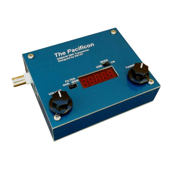
The KD1JV Pacificon
A DSB/CW transceiver for 40 meters.
Featuring: Wide tuning range digital VFO with 5 digit LED readout.
Direct Conversion receiver
~5 watt CW/PEP transmitter
The CalQRP club wanted a simple transceiver with voice capability for a Pacificon build-a-thon. The
goal was to have a QSO party using the project at the end of the build-a-thon.
The other two design goals were low cost, reasonably simple design and hopefully most can build
it in under two hours. DSB was chosen since it's a lot simpler to implement then a SSB transceiver
and is somewhat more effective than AM.
Conventional wisdom says two DSB stations can't talk to each other if both use a Direct
Conversion receiver. This is not true.
What is true is that the two stations need to match each other's frequency exactly. Or at least
really close. As the center frequency of one or the other (or both) stations start to drift apart, the
beat note of each side band starts to separate, with annoying results.
The problem with minimalist DSB designs is that they often used an Analog VFO of questionable
stability. So, keeping two home brew DSB stations on the same frequency was frustrating, hence
the bad rap.
By using the inexpensive Si5351 clock chip for the VFO and the various additional functions a
microprocessor adds, The Pacificon becomes a practical DSB rig.
The firmware is written with the Arduino IDE. The MEGA328P processor comes with the bootloader
installed, making it compatible with the UNO board for reprogramming. The Arduino sketch is
available to tinker with.
A Baofeng UV3R, (not UV3R+), single plug microphone is required for voice operation. These are
available on ebay for $5 to $10 depending on who you buy from and how long you want to wait
for it.
Page 1 of 19
pacificon_assy_041621.pdf
Advertisement

Related Manuals for QRPGuys Pacificon KD1JV


Summary of Contents for QRPGuys Pacificon KD1JV
- Page 1 The KD1JV Pacificon A DSB/CW transceiver for 40 meters. Featuring: Wide tuning range digital VFO with 5 digit LED readout. Direct Conversion receiver ~5 watt CW/PEP transmitter The CalQRP club wanted a simple transceiver with voice capability for a Pacificon build-a-thon. The goal was to have a QSO party using the project at the end of the build-a-thon.
- Page 2 Specifications: DSB/CW Transceiver for 40 meters. Tuning range 500 kHz to 30 MHz (actual range limited by band filter characteristics) Direct Conversion (DC) receiver. Receiver MDS: ~0.5 uV Audio Bandwidth: Wide: 4,000 Hz Narrow : 1,000 Hz ...
- Page 3 Parts list: QTY Value Code QTY Value Code 5.6 ohms Grn/Blu/Gld/Gld 100 nF (.1uF) 10 ohms Brn/Blk/Blk/Gld 10 nF (.01 uF) 51 ohms Grn/Brn/Blk/Gld 1 nF (.001uF) 150 ohms Brn/GRN/BRN/Gld 680 pF 2.2K Red/Red/Red/Gld 330 pF 4.7K Yel/Vio/Red/Gld 68 pF Brn/Blk/Org/Gld 47 pF Red/Red/Org/Gld...
- Page 4 [] Solder U4, the Si5351A smd component first. Position as shown below. Note orientation of Pin1. Be sure there are no solder bridges between pins. Use Solder Wick® if necessary to remove any excess. Resistors: Some values who's color codes are very similar are easy to mix up. It's important to pay attention to the multiplier band to make sure you have the correct decade.
- Page 5 [] 331 - C2, C3, C37 [] 681 - C4, C27 [] 68 - C6 [] 103 – C13, C22, C26, C30, C32 [] 102 – C7, C12, C15 [] 47 – C18, C20 Crystals: [] 25.000 - X1 [] 16.000 - X2 Sockets: [] 8 pin DIP –...
- Page 6 [] BS170 – Q7, Q8, Q9, Q10, Q11 [] 2N3904 – Q1, Q6 [] 2N3906 – Q5 [] 78L05 - U7 [] 78L09 – U2 [] V1 2K trimmer Electrolytic caps: [] 1 uF/25V – C24, C29, C33 – long lead is plus [] 100 uF/16V –...
- Page 7 Top side: Only three parts to install now. [] EC1 – encoder [] V2 – volume pot [] S1, S2 – SPDT slide switch. Add a couple of temporary jumpers: There are provisions for adding an optional ON/OFF switch and external speaker/headphone jack.
- Page 8 Initial Power up: Before you apply power to the circuits, spend a few moments to inspect your work. Soldering issues are the most common cause of a kit not working first and every time. Grounds take a little more heat than connections to tracks, so look at these carefully to make sure the solder didn't just stick to the lead.
- Page 9 Transmitter testing: The bias current for the linear PA needs to be set. You might as well connect up a power meter and dummy load now. Connect an ampmeter in series with your power supply. The 200 ma. setting should be fine.
- Page 10 Packaging the board: A custom PCB enclosure is available from QRPGuys. Simple, light and with labeled controls, it is a good option. If you don't mind doing some metal work, the board will fit into a 110mm X 88 mm X 38 mm extruded aluminum box, which is commonly available on ebay.
- Page 11 Tuning Encoder Push Button: The tuning encoder has a built in push button which is used to select several options. 1 – Change tuning rate. 2 – Enable/disable RIT. 3 – Enable CW mode. 4 – Store a custom default power on frequency. 5 –...
- Page 12 5 – Calibration: A 5 second push of the Encoder actives Calibration mode Release the Encoder when [CAL ] is displayed. The VFO reference oscillator can now be tuned with the encoder to calibrate the frequency. This can be done in one of two ways. 1.
- Page 13 Voice DSB operation: Plug in the speaker/mic. Make sure the mode switch is in the DSB position. Push the button on the mic and talk. There is no modulation control, it is based on how loud you talk. Speak in a normal conversational level.
- Page 14 Calling CQ is the easier option, as all you need to do is find a clear frequency and activate RIT. If there's a contest going on, and the band is crowded, I'd find another rig to use! Adding a linear: Let’s face it, 2.5 watts PEP isn't a whole lot of power for voice.
- Page 15 With my ladder line feed “88” and MFJ balance line tuner, I can get reception of stations all the way down into the AM broadcast band. One does have to strain a bit to hear the AMBC stations. One characteristic of a Direct Conversion receiver is it will also detect stations at harmonics of the LO frequency.
- Page 16 Side panel drilling dimensions: Below the dimensions shown in the Y axis are referenced to the bottom of the board. To this one would have to add the thickness of the board (0.061”) plus the board mounting spacers and the thickness of the front panel to get the proper Y distance.
- Page 17 Wiring note: The speaker jack is shown facing up for connection clarity. Install the jack with the pins down. Use the two 4” cable ties to bundle the wires close to the pcb. This reduces the strain on any individual wire. ] Plug J4 and J5 pigtails into the correct board receptacles, and slide the top Pcb assembly into the chassis, securing it with the four 3mm x 10mm long bottom screws.
- Page 18 Sometime it will look like you made a good connection, but the solder really only stuck to the component lead and didn't flow into the pad on the board. These can be a little tough to spot. Another common area for a problem is not properly tinning the magnet wire on the toroid windings.
- Page 19 Page 19 of 19 pacificon_assy_041621.pdf...
Need help?
Do you have a question about the Pacificon KD1JV and is the answer not in the manual?
Questions and answers