Table of Contents
Advertisement
Quick Links
‡ SIGNET
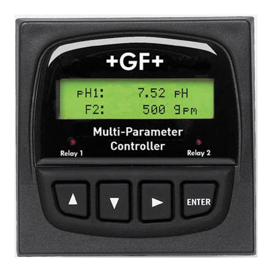
8900 Multi-Parameter Controller
Contents
Important Safety Information ................................................................................................................. 2
1.
Description ............................................................................................................................................... 3
2.
Compatibility ............................................................................................................................................ 3
3.
System Overview ..................................................................................................................................... 4
4.
Specifications .......................................................................................................................................... 5
5.
Installation and Basic Functionality ...................................................................................................... 7
5.1
Unpacking ....................................................................................................................................................................... 7
5.2
Tools and Equipment Required: ................................................................................................................................... 7
5.3
Plug-in Modules ............................................................................................................................................................. 7
5.3.1
I/O Module ....................................................................................................................................................................... 8
5.3.2
Power Module .................................................................................................................................................................. 8
5.3.3
Output Module ................................................................................................................................................................. 9
5.3.4
Relay Module ................................................................................................................................................................... 9
5.3.5
External Relay Module ................................................................................................................................................... 10
5.4
Mounting the Base Unit ............................................................................................................................................... 11
5.4.1
Panel Mounting .............................................................................................................................................................. 11
5.4.2
Mounting Accessories .................................................................................................................................................... 12
6.
Wiring ..................................................................................................................................................... 13
6.1
I/O Module (3-8900.401-X) ........................................................................................................................................... 13
3
6.1.1
L™? ............................................................................................................................................................... 13
6.1.2
Wiring Topologies ........................................................................................................................................................... 13
6.1.2.1 Point-to-point .................................................................................................................................................................. 13
6.1.2.2 Daisy-chain .................................................................................................................................................................... 13
6.1.2.3 Multi-drop ....................................................................................................................................................................... 14
6.1.2.4 Combinations ................................................................................................................................................................. 14
6.1.2.5 Accessory Junction Boxes ............................................................................................................................................. 14
6.1.3
Maximum Cable Lengths ............................................................................................................................................... 14
6.1.3.1 Signal Type: Frequency ................................................................................................................................................. 14
6.1.4
I/O Module (3-8900.401-X) Wiring Diagrams ................................................................................................................. 16
6.2
Power Module (3-8900.402-X) ..................................................................................................................................... 19
6.3
Output Module (3-8900.405-X) .................................................................................................................................... 19
6.4
RS232 Communication Module (3-8900.404-1) ......................................................................................................... 19
6.5
Relay Module (3-8900.403-X) ....................................................................................................................................... 20
6.6
External Relay Module ................................................................................................................................................. 20
7.
Operational Overview ........................................................................................................................... 21
7.1
Keypad Functions ........................................................................................................................................................ 21
7.2
General Operation Flowchart ...................................................................................................................................... 21
7.3
View Mode .................................................................................................................................................................... 22
7.3.1
Channel Types ............................................................................................................................................................... 22
7.3.2
Measurement Display Screens ...................................................................................................................................... 22
7.3.3
Derived Functions .......................................................................................................................................................... 23
7.3.4
Analog Output Values .................................................................................................................................................... 23
7.3.5
Relay Status Indicators .................................................................................................................................................. 23
7.3.6
Memo ............................................................................................................................................................................. 23
7.3.7
System Configuration ..................................................................................................................................................... 24
7.3.8
Menu Directory ............................................................................................................................................................... 24
3
L ............................................................................................................................................................. 15
Multi-Parameter
C1
2.50 µS/cm
F2
58.43 GPM
Relay 1
Relay 2
ENTER
Advertisement
Table of Contents

Related Manuals for Signet 8900

Summary of Contents for Signet 8900
-
Page 1: Table Of Contents
6.1.3.1 Signal Type: Frequency ..............................14 6.1.3.2 Signal Type: S L ................................15 6.1.4 I/O Module (3-8900.401-X) Wiring Diagrams ......................... 16 Power Module (3-8900.402-X) ............................. 19 Output Module (3-8900.405-X) ............................ 19 RS232 Communication Module (3-8900.404-1) ......................19 Relay Module (3-8900.403-X) ............................20 External Relay Module .............................. -
Page 2: Important Safety Information
CAUTION Solid State Relays label (AC ONLY or DC ONLY) is packaged with each Power Rating: Module and should be applied to the 8900 rear panel as 50 mA 30V DO NOT attempt to connect both illustrated. AC and DC at the same time ‡... -
Page 3: Description
L™ output including pH, ORP, conductivity/resistivity, pressure, temperature, and level. Up to two of the possible four input channels may be used for any combination of the many +GF+ SIGNET flow sensors with frequency output. See Section 2 Compatibility for sensor models and other devices available for use with this controller. -
Page 4: System Overview
3. System Overview The most basic 8900 system consists of a Base Unit, an I/O Module and a Power Module. Outputs and relays are optional. Each item is ordered separately. The variety of configurations attainable from this modularity is extraordinary. -
Page 5: Specifications
Panel Gasket: Silicone Sponge Output Power to Sensors: Window: Self-healing polyurethane-coated 5VDC up to 40 mA total polycarbonate Terminal type: Screw clamp, removable via plug-in modules Keypad: 4-buttons, highly tactile and audible Injection-molded silicone rubber seal ‡ SIGNET 8900 Multi-Parameter Controller... - Page 6 1.00 kg (2.25 lb.) Power Module 0.12 kg (0.25 lb.) I/O Module 0.12 kg (0.25 lb.) Output Module 0.12 kg (0.25 lb.) Relay Module 0.12 kg (0.25 lb.) RS232 Communication Module 0.12 kg (0.25 lb.) ‡ SIGNET 8900 Multi-Parameter Controller...
-
Page 7: Installation And Basic Functionality
• If the 8900 Base Unit will be mounted in a panel, plug-in modules may be installed either before or after the base unit is mounted. If the 8900 Base Unit will be mounted using the accessory Wall Mount Bracket, first install plug-in modules. -
Page 8: I/O Module
Freq. Input 2 (Red) S 3 L S L (Red) as Outputs 1 & 2 in the 8900 menus. Any and all analog outputs are freely assignable Input GND (White/Shield) to any channel. All analog outputs available from the 8900 are isolated. -
Page 9: Output Module
Voltage outputs are independently software selectable for operation from 0 to 5 or 0 to 10 VDC. • NOTE: Upon initial introduction of the 8900 product series, the RS232 Communication Module will be limited to Clone Mode functionality. This feature requires the accessory DB-9 Crossover Cable and allows an 8900 instrument to adopt all software settings of another 8900 instrument. -
Page 10: External Relay Module
INPUT OUTPUT 24VDC • The 8900 will support up to eight (8) relays, though only four actually fit directly inside its compact DIN enclosure! 8059 External Relay Modules of either two or four relays may be connected to the 8900 via S... -
Page 11: Mounting The Base Unit
5.4 Mounting the Base Unit Quick-clip The 8900 may be mounted in a panel, on a wall, or on virtually mounting 96 mm/3.78 in. bracket any surface including shelves, racks and pipes. All methods of mounting the 8900 make use of the +GF+ SIGNET Quick-clip for Multi-Parameter 23.45 µS/cm... -
Page 12: Mounting Accessories
5.4.2 Mounting Accessories Refer to section 5.4.1 regarding the use of the Quick-clip for securing the 8900 instrument in panel adapters or brackets. Mfr. Part No. Description 3-8050.395 Splashproof rear cover • Use in conjunction with liquid tight connector kits to seal wiring ports. -
Page 13: Wiring
6. Wiring All wiring connections to the 8900 are made via the removable terminals of the plug-in modules. This section contains instructions and diagrams for wiring each type of module. Several helpful tables, explanations and recommendations are also provided. In general: •... -
Page 14: Multi-Drop
All of the sensors in the table below are compatible with the 8900. The three models limited to 60 m (200 ft.) are self-powered sensors. The 8900 automatically provides power to the others via the I/O Module (normal sensor wiring). -
Page 15: Signal Type: S
From an instrument’s EMI filtering capability, and its capacity to provide power to these devices, maximum cable length guidelines can be established. For the 8900, these guidelines are defined here. Maximum total cable length from S... -
Page 16: I/O Module (3-8900.401-X) Wiring Diagrams
6.1.4 I/O Module (3-8900.401-X) Wiring Diagrams Determine the number of frequency inputs and the number of separate S L™ digital signal lines to be wired directly to the I/O Module, then use the table below and the corresponding wiring diagram(s) for instruction. - Page 17 3-8900.621C I/O Module 3-8900.401-X +5VDC (Black) Frequency Input Freq. Input (Red) GND (Shield) +5VDC (Black) Frequency Input 2 S 3 L“ device Freq. Input 2 (Red) S 3 L S L (Red) Input GND (White/Shield) S 3 L device +5VDC (Black)
- Page 18 3-8900.621C I/O Module 3-8900.401-X +5VDC (Black) Frequency Input Freq. Input (Red) GND (Shield) +5VDC (Black) Frequency Input 2 Freq. Input 2 (Red) S 3 L S L (Red) Input GND (White/Shield) +5VDC (Black) S 3 L S L (Red) Input...
-
Page 19: Power Module (3-8900.402-X)
• Active 4-20 mA Loop Output Module Passive 4-20 mA Loop wiring The DC power required for the loop is supplied by the 8900. No additional power source is needed. • Passive 4-20 mA Loop Output Module The DC power required for the loop must be provided by an external source. -
Page 20: Relay Module (3-8900.403-X)
6.5 Relay Module (3-8900.403-X) The alarm is OFF during normal operation, and will go ON according to 8900 Relay settings. Solid State Relays (non-mechanical switches) Normally open/closed operation: Software selectable AC or DC Max. pulse rate: 600 pulses per minute power (volumetric pulse &... -
Page 21: Operational Overview
"_" Function 7.2 General Operation Flowchart The four display modes of the 8900 are layered as shown in the flowchart below. Keypad symbols illustrate basic navigation within and between these modes. • View: This is the default mode upon supplying power to the instrument. After system set-up is complete, all measurement values for each channel, plus the status of any analog outputs and relays will be available. -
Page 22: View Mode
7.3.2 Measurement Display Screens • The 8900 has a two-line display screen, like all the other ProcessPro instruments, but 8900 users choose to display either one or two measurements per screen. • In fact, four measurement display screens are independently configurable for single-measurement format, or dual-measurement format, according to user preference. -
Page 23: Derived Functions
Function Type of the Options menu. • The 8900 allows up to three derived functions to be used for display and control at any one time. An example of the display for derived functions is shown here. This format cannot be modified. -
Page 24: System Configuration
The Menu Directory may also be reached from any item in View by pressing and holding the ENTER button for two seconds. • The Menu Directory provides access to the seven separate menus of the 8900: System Setup, Channel Settings, Hold Inputs, Relay, Output, Calibration, and Options. -
Page 25: Menus
When power is applied to the 8900 it automatically recognizes the types of plug-in modules installed and adjusts menu content accordingly. For example, there will be no reference to channels 3 and 4, in any of the menus, if an I/O Module containing only two inputs is installed. -
Page 26: Pre-Configuration Guidelines
Note: b. and c. can only be remedied after sensors are connected. Remove power from the unit. All settings will be saved indefinitely in the non-volatile memory. 10. 8900 systems may be transported from one location to another with plug-in modules installed. 8.1.2... -
Page 27: System Setup
8.2 System Setup In terms of getting started and making measurements, System Setup is the most important menu in the 8900. And, the first and most important item in this menu is the Channel Type selection. Accessibility or content of virtually all items in every menu is reliant upon the association of measurement types with channels. -
Page 28: Channel Settings
Lock Off: No EDIT code required to reset the Resettable totalizer to zero. Lock Off > Dampens display, output and relay response rates for this channel. F1 Average: Off: Near instantaneous updates > Low: 4 s Med: 8 s Hi: 32 s ‡ SIGNET 8900 Multi-Parameter Controller... -
Page 29: Orp
Select decimal location for this conductivity display: **.*** > XXXXX. XXXX.X XXX.XX XX.XXX X.XXXX Dampens display, output and relay response rates for this channel. C1 Average: Off: Near instantaneous updates > Low: 4 s Med: 8 s Hi: 32 s ‡ SIGNET 8900 Multi-Parameter Controller... - Page 30 Select the unit of measure for this temperature channel: °C > Dampens display, output and relay response rates for this channel. T1 Average: Off: Near instantaneous updates Low: 4 s Med: 8 s Hi: 32 s > ‡ SIGNET 8900 Multi-Parameter Controller...
- Page 31 If Volume measurement will be displayed a percentage, set the full scale value (100%) in units 0.0000 gal > of measure. Spec Gravity L1: If a pressure sensor is used for Level measurement, enter the specific gravity of the fluid. 1.0000 > ‡ SIGNET 8900 Multi-Parameter Controller...
-
Page 32: Hold Inputs
Hold Input: however). Useful during calibration to avoid false alarms and unwanted engagement of Conductivity C1> control equipment. Un-Hold Input: Manually release the channel on hold. (Appears only when a channel is held) Conductivity C1> ‡ SIGNET 8900 Multi-Parameter Controller... -
Page 33: Conductivity
If relay mode is Prop Pulse, PWM or Window: Enter the low-end setpoint. If relay mode is Prop Pulse, PWM or Window: Enter the high-end setpoint. If relay mode is PWM, set the pulse period. Minimum 0.1 s, maximum 3240 s (54 minutes) ‡ SIGNET 8900 Multi-Parameter Controller... - Page 34 If Relay mode is pulse: Set the duration of the relay pulse. Minimum 0.1 s, maximum 3240 s (54 minutes) For solid state relays only: N.C. = Normally Closed N.O. = Normally Open Manually toggle relay to test operation. ‡ SIGNET 8900 Multi-Parameter Controller...
-
Page 35: Output
Test Output 1: If 4-20 mA, test limits are 3.8 mA to 21.0 mA. If 0-5 VDC, test limits are 0.00 to 5.50 VDC. > If 0-10 VDC, test limits are 0.00 to 10.50 VDC. ‡ SIGNET 8900 Multi-Parameter Controller... -
Page 36: Calibration
Volume > Volumetric Cal Select to perform volumetric calibration. > Press ENTER to start the volumetric calibration period. The 8900 starts counting pulses from Press <ENTER> the flow sensor. to Start Cal Press <ENTER> Press ENTER to stop the volumetric calibration period. The 8900 stops counting pulses from the flow sensor. -
Page 37: Orp
Calibration: If Channel type = pH SENSOR: Select to perform calibration at the sensor via 2750 EasyCal. pH1 Cal at: INSTRUMENT: Select to perform calibration at the 8900 via the steps below. Sensor > If Cal at Instrument is selected, the following menu items appear: Place sensor in any pH buffer. -
Page 38: Conductivity
Calibration: If Channel type = Conductivity C1 Cal at: SENSOR: Select to perform calibration at the sensor via 2850 EasyCal. INSTRUMENT: Select to perform calibration at the 8900 via the steps below. Sensor > If Cal at Instrument is selected, the following menu items appear: Set Conductivity Place sensor in any conductivity test solution. -
Page 39: Options
Select the two measurements to be used for this function. ORP1-ORP2 > Select "YES" to download all settings from another 8900. Both units must be equipped Clone with the same plug-in modules, including the RS232 Comm Module. The DB-9 crossover Instrument: >... - Page 40 Notes ‡ SIGNET 8900 Multi-Parameter Controller...
-
Page 41: Appendix A: Derived Functions
Appendix A: Derived Functions When two or more measurements of the same type are present, the 8900 can calculate several derived functions from like pairs. Up to three derived Functions can be defined and used as the source for display and output functions. -
Page 42: Appendix B: Level System Configuration
Appendix B: Level System Configuration The +GF+ SIGNET 2450 Pressure sensor can be used to calculate level values. The following information is required for this mode: Determine where you want the level measurement to start. This is the Zero reference point (Z). - Page 43 • Simpler sections require fewer defining points. Note that the cylinder requires only custom points 9 and 10. Technical Reference for Level measurement Level, volume and mass calculations performed by the 8900 Volume calculations include: Vertical cylinder: V = þ • d •...
-
Page 44: Appendix C: Conductivity/Resistivity Application
(150 x (48 - 25)) - (205 x (23 - 25)) 3860 • The 8900 calculates PPM or PPB by dividing the µS value by a TDS Factor that you define. • TDS factors can vary widely, ranging from 1.50 to 2.50 µS per PPM. -
Page 45: Appendix D: Usp Limits
Using the USP function USP setpoints are defined as a percentage below the USP limit, so a USP alarm is always a HIGH alarm. The 8900 can be set to warn you if the conductivity approaches within a set percentage of the USP limit. -
Page 46: Appendix E: Relay Mode Descriptions
Proportional Pulse mode varies the frequency of pulses in direct 100 pulses proportion to minimum and maximum setpoints. • The 8900 does not allow use of this mode for Pressure applications. Example: • The output will be 0 pulses/min. at process values less than 5.0. -
Page 47: Appendix F: 8900 Display Messages
Appendix F: 8900 display messages Display Message Explanation Press <ENTER>To Stop Cal This will stop the flow counting for volumetric cal Enter Volume: Enter a volume to calculate flow K-Factor New K-Factor: New K-Factor is calculated in flow vol. Cal... - Page 48 Front Face Panel Gasket ‡ SIGNET Signet Scientific Company, 3401 Aerojet Avenue, El Monte, CA 91731-2882 U.S.A. • Tel. (626) 571-2770 • Fax (626) 573-2057 For Worldwide Sales and Service, visit our website: www.gfsignet.com • Or call (in the U.S.): (800) 854-4090 GEORGE FISCHER ‡...
Need help?
Do you have a question about the 8900 and is the answer not in the manual?
Questions and answers