Table of Contents
Advertisement
Advertisement
Table of Contents

Related Manuals for VICI CM-2016


Summary of Contents for VICI CM-2016
- Page 1 DIGITAL CLAMP METER OPERATION...
-
Page 2: Table Of Contents
OPERATION MANUAL CONTENTS I.SUMMARY..2.SAFETY NOTICE 3.FEATURES... 3.I. GENERAL FEATURES 3.2. TECHNICAL FEATURES 4.OPERATlON · 4.I.PANEL DESCRIPTlON 4.2.DCV MEASUREMENT 4.3.ACV MEASUREMENT 4.4.DCA MEASUREMENT 4.5.ACA MEASUREMENT 4.6. RESISTANCE MEASUREMENT 4.7. DIODE AND CONTlNUlTY TEST 4.8. CAPACITANCE TEST 4.9. FREQUENCY MEASUREMENT 4.10. -
Page 3: I.summary
2. SAFETY NOTlCE Tbe meter is designed to be in compliance with IEC1010-I (EN61010-1), pollution 2, CAT.III 600V and UL3111-1. Please read this manual carefully before operation. 2-1.SAFETY SYMBOLS " "CAUTION: Refer to manual before operation. " " Low battery indication. "... -
Page 4: Features
3.FEATURES 3.1. GENERAL FEATURES 3.1.1. Display: LCD. 3.1.2. Max. display: 6000 digits, and auto polarity display. 3.1.3. Clamp open max.28mm. 3.1.4. Over-range display: "OL". 3.1.5. Data hold. 3.1.6. Relative Value measurement. 3.1.7. Sampling rate: times/sec. 3.1.8. The symbol " " appears when battery is low. - Page 5 3.2.4. AC Voltage (ACVrms) Range Accuracy Resolution 600mV ±(1.5% of reading + 5) 0.l mV 0,001 V ±(1,0% of reading + 5) 0,01 V 600V 0,1 V Input impedance: 10MΩ. Overload production: 1000Vrms Frequency response: 750 V at 40Hz - 1 kHz, other ranges 40Hz - 400Hz. 3.2.5.
- Page 6 3.2.8. Capacitance (C) Range Accuracy Resolution 60 nF 10 pF 600 nF 100 pF (3.5% + 20) 6 µF 1 nF 60 µF 10 nF 600 µF 100 nF (5.0% + 10) 6000 µF 1 µF Over load protection: 250Vrms. WARNlNG: DO NOT input voltage in this range.
-
Page 7: Operatlon
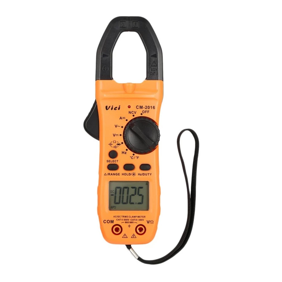
4. OPERATION lNSTRUCTIONS 4.1. PANEL lLLUSTRATON (Fig.l) 1)Clamp jaw:0-600A DCcurrent, ACcurrent and NCVdetecting device. 2)Clamp gunlock:Press the gunlock to open clamp jaw. 3)Hand protection: A safe design to protect users from touching the dangerous area. 4)Clamp light:Turn on the clamp light to light up the tested area in the dark to prevent danger. - Page 8 HOLD/ key: LD key is to reading", working in response to trigger. hold " Press this key for time to lock reading. Press any other keys to exit HOLD function. Press this key for more than two seconds turn LCD backlight and clamp light at the same time.
-
Page 9: Dcv Measurement
(9) V/Ω.input terminal: The red one positive input terminal for voltage, resistance, diode, capacitance, frequency and temperature measurements.lt is also COM terminal for GND input.The black one is negative input terminal. (10) Carrying belt. 4.2. DCV MEASUREMENT (I) Turn the rotary function switch to V position. -
Page 10: Dca Measurement
4.4.DCA MEASUREMENT (I) Turn the rotary function switch to A position. The meter is default at DC A measurement after power on. Press SELECT to switch between AC or DC measurement. (2) When the meter is used in a strong magnetic field, the readings could be unstahle or inaccurate. -
Page 11: Aca Measurement
4.) Switch on the testing wire. Read after clamp meter remains stable. 5.) When measuring current, to get more accurate readings, the ambient temperature must be 0 to 40°C. 4.5. AC A MEASUREMENT (I) Turn the rotary function switch to A position.The meter is default at DC A measurement after power on. -
Page 12: Diode And Contlnulty Test
on the two sides of the testing resistor. (6) DO NOT input voltage in the resistance range. 4.7. DIODE AND CONTlNUITY MEASUREMENTS (I) Turn the rotary function switch to " " position. Press SELECT to choose diode measurement. (The symbol appears on LCD.) Plug the red test lead in to "VΩ... -
Page 13: Capacitance Test
the black test lead i nto COM terminal. Please note that the red test lead is for positive polarity. NOTE: (I) DO NOT input voltage or signal in the capacitance range. (2) If there is remaining values on LCD before measurement, to ensure measurement accuracy, press REL keytoclear it. -
Page 14: Temperature Test
4.11. Non-Contacnt Voltage (NCV) Detect WARNING: This function could be affected by different external interference sources, and then the alarm is activated by wrong slgnal. The Measurement result is for reference only. (I) Turn the rotary function switch to "NCV" position. When the testing circuit is placed above the meter. -
Page 15: Auto Power Off
(4) Take out balteries if the meter is meant to be not used for a longtime. NOTE: When the LCD displays " ",please replace the battery in tirne as per below steps. (I) Screw off the fixing screws. Remove the battery cover. (2) Take off the two 1.5V batteries and replace with new ones.
Need help?
Do you have a question about the CM-2016 and is the answer not in the manual?
Questions and answers