Advertisement
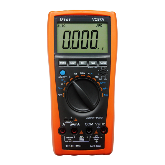
DIGTAL MULTIMETER
Operation Manual
1.
General Description
This is a 3 3/4 digital multimeter with high stablility and performance. It uses a LCD with
20mm high figure, which makes the reading clearer and the operation more convenient. It
can test DCV, ACV, DCA, ACA, resistance, capacitance, frequency, NCV, duty cycle,
temperature, diode, and continuity. This meter also designed with functions including unit
symbol display, data hold, lighting, auto range, auto power off and warning functions. To
assure high accuracy and resolution, it adopts integrated circuit 8-bit microprocessor and a
dual integral A/D conversion as LCD driver, giving high resolution and high accuracy. It is
an ideal tool for labs, factories and radio-technology.
2.
Safety Instructions
The instrument VC97A is designed in compliance with IEC1010 standard (safety standard
issued by International Electro technical Committee). Please read the following safety
instructions before operation.
2.1 Check the connection and insulation of test leads to avoid electric shock.
2.2 To avoid electric shock and damage to the meter, do not input voltage exceeding rated
value.
2.3 When measuring voltage higher than DC 60V or AC 40V, please be
electric shock.
2.4 Select correct function and range to avoid wrong operation.
2.5 Move the test leads away from test points when switching to other function.
2.6 Don't input voltage in current terminal.
2.7 Don't make any modification to the circuit. It may damage the meter or jeopardize
safety.
2.8 Safety symbols:
"
" High voltage, "
" GND, "
battery indication.
3.
Features
3.1 General Characteristics
3.1.1 Display: LCD;
3.1.2 Max display: 4000 (3 3/4 digits, automatic polarity, and unit symbol display);
3.1.3 Measurement method: Analog to digital converter (in micro processor ADC+MCU);
3.1.4 Sampling rate: approx.3 times/sec.
3.1.5 Over-range display: "OL" displayed.
3.1.6 Low battery indicator: "
3.1.7 Working environment: (0~40)℃, relative humidity: <80%;
3.1.8 Store condition: (-10~50)℃, relative humidity: <80%
3.1.9 Battery: 2 pieces 1.5V battery ("AAA" 7# battery);
3.1.10 Dimension: 185×93×35mm (length x width x height);
3.1.11 Weight: approx. 290g (including battery);
3.1.12 Accessories: test leads, TP01 thermocouple, user manual, holster, gift box, and
2*1.5V batteries.
3.2 Technical Features
3.2.1 Accuracy: ± (a% × reading + digits). To assure accuracy, the ambient temperature
should be (23±5) ℃, relative humidity <75%. One year accuracy is guaranteed since
production date.
3.2.2 DC Voltage(DCV)
Range
400mV
4V
40V
400V
1000V
Input impedance: at 400mV range >40MΩ, at other ranges is 10MΩ.
Overload protection: 1000VDC or 750VAC peak value.
careful
and avoid
" Dual insulation, "
" Refer to manual, "
" Low
"
Accuracy
Resolution
0.1mV
1mV
±(0.5%+5d)
10mV
100mV
±(1.0%+5d)
1V
3.2.3. AC Voltage(ACV)(True RMS)
Range
Accuracy
400mV
±(1.5%+10d)
4V
40V
±(0.8%+10d)
400V
750V
±(1.0%+10d)
Input impedance: at 400mV range >40MΩ, at other ranges is 10MΩ.
Overload protection: 1000VDC or 750VAC peak value.
Frequency response: at 750V range: (40~1000)Hz, at other ranges: (40~2000)Hz
Displaying: True RMS response (calibration based on sine wave RMS)
3.2.4 DC Current(DCA)
Range
Accuracy
400uA
4000uA
±(1.0%+5)
40mA
400mA
4A
20A
±(2.0%+5)
Maximum voltage drop: 400 mV for full mA range, 200 mV for full A range.
Maximum input current: 20A (within 10 seconds).
Overload protection: 0.5/250V fuse and 13A/250V fuse.
3.2.5 AC Current (ACA)
Range
Accuracy
400uA
4000uA
40mA
±(1.5%+10)
400mA
4A
20A
±(2.0%+10)
Maximum voltage drop: 400 mV for full mA range, 200 mV for full A range.
Maximum input current: 20A (within 10 seconds).
Overload protection: 0.5/250V fuse and 13A/250V fuse.
Frequency response: at 20A range: (40~100)Hz, at other ranges: (40~400)Hz.
Resolution
0.1mV
1mV
10mV
100mV
1V
Resolution
0.1μA
1μA
10μA
100μA
1mA
10mA
Resolution
0.1μA
1μA
10μA
100μA
1mA
10mA
Advertisement
Table of Contents

Related Manuals for VICI VC97A


Summary of Contents for VICI VC97A
- Page 1 Resolution 400mA 100μA 400mV 0.1mV Safety Instructions The instrument VC97A is designed in compliance with IEC1010 standard (safety standard ±(0.5%+5d) ±(2.0%+10) 10mA 10mV issued by International Electro technical Committee). Please read the following safety Maximum voltage drop: 400 mV for full mA range, 200 mV for full A range.
- Page 2 The continuity beeper is on. 3.2.6 Resistance(Ω) 3.2.9 Transistor (hFE) it can measure the MAX., MIN. value and MAX-MIN difference value between MAX. and MIN.. Range Accuracy Resolution Measurement Display Range Test conditions Auto power off symbol. Low battery indication. Warning: To avoid error 400Ω...
- Page 3 and enter sleep mode. One minute before sleep mode, the buzzer will beep for 5 times and the built-in buzzer will alarm. If the LCD displays “OL”, it means the current is over range. Now you need to select to remind user. Press any button will exit the sleep mode. Be careful while measuring a high voltage circuit.
- Page 4 should take out the battery to avoid leakage damage. signal source or the load which is tested (It should over 3Hz). Ω, the buzzer sounds. When “ ” symbol is displayed, you should replace the battery according to the 4.8.3 Press “Hz/DUTY” key to choose frequency/duty cycle measurement, LCD will display NOTE: following steps: the frequency or duty cycle of the tested signal source.
Need help?
Do you have a question about the VC97A and is the answer not in the manual?
Questions and answers