Table of Contents
Advertisement
Quick Links
Advertisement
Table of Contents

Related Manuals for Dennis VERTICUT T.T.


Summary of Contents for Dennis VERTICUT T.T.
- Page 1 VERTICUT T.T. VERTICUTTER INSTRUCTION MANUAL DENNIS, Ashbourne Road, Kirk Langley, Derby, DE6 4NJ, United Kingdom Telephone:- 01332 824777 Fax:- 01332 824 525 E-mail:- sales@dennisuk.com E-mail:- spares@dennisuk.com SP20007_REV_0 www.dennisuk.com 04/12...
-
Page 3: Declaration Of Conformity
Serial Numbers MAKE A NOTE OF THE SERIAL NUMBERS OF YOUR MACHINE & ENGINE AND ALWAYS NOTE QUOTE THEM IN ANY COMMUNICATION WITH PERSONNEL AT DENNIS. The reliability and quality of performance of the depends upon some simple care maintenance carried out regularly. -
Page 4: Table Of Contents
Contents Page Product Application Matrix ..............................2 Declaration of Conformity ..............................3 Serial Numbers ..................................3 Introduction ................................... 3 Technical Data ..................................4 Machine Description ................................5 Important Safety Instructions ..............................6 Controls ....................................7 Operating Instructions ..............................8 - 9 General Adjustments ................................ -
Page 5: Machine Description
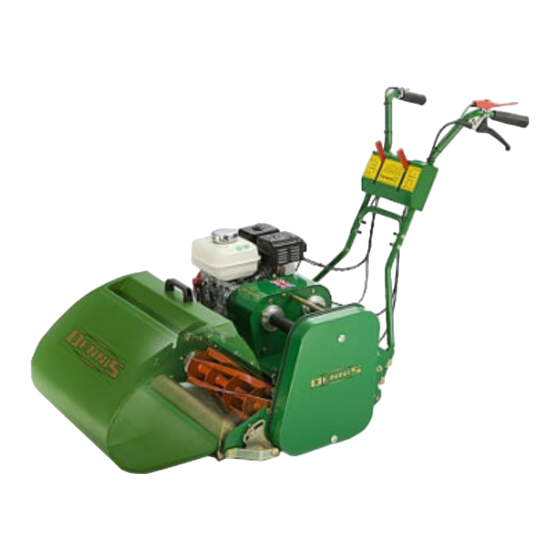
Manufactured with a 20” (51cm) width, this range of machines is powered by a 5.5hp air cooled, single cylinder, four stroke petrol engine. The rear roller and cutter are controlled independently via belt clutches operated from the console on the upper handle In the design of the machine, special attention has been given to the importance of easy service and maintenance with the construction based on a sectional assembly system. -
Page 6: Important Safety Instructions
In order to operate the machine safely please follow these Health and Safety guidelines. READ THE INSTRUCTIONS CONTAINED IN THIS MANUAL WITH CARE. IF YOU ARE IN ANY DOUBT PLEASE ASK YOUR EMPLOYER OR CONTACT US DIRECT AT DENNIS. Be familiar with the controls and the proper use of the equipment. -
Page 7: Controls
Controls This switch stops the engine and can be used to do so at anytime during the operation of the machine. Ensure it is in the position before attempting to start the engine. This is an operator presence control. The engine will tick over without need for this to be depressed when the cutter and drive are disengaged. -
Page 8: Operating Instructions
BEFORE YOU OPERATE THIS MACHINE YOU MUST READ AND STUDY THIS MANUAL. IF YOU ARE IN ANY DOUBT PLEASE ASK YOUR EMPLOYER OR CONTACT US DIRECT. Before commencing ensure the turf is free from stones or other obstructions which may damage the cutter unit. Set the height of cut to the required level (see page 10) Check the engine. - Page 9 Depress the (Item 15) Push the (Item 12) forwards. (Item 14) forwards. Set the to increase / reduce speed. (Item 14) Pull the (Item 16) backwards. Release the (Item 15) RELEASING THE “DEADMANS CONTROL LEVER” WITH THE CUTTER ENGAGED WILL NOTE CAUSE THE ENGINE TO STOP Used from ground +3mm to ground -3mm to control thatch, cutting lateral growths and standing up lying grasses ready for...
-
Page 10: General Adjustments
General Adjustments Always stop the engine before adjusting the height of cut. Failure to do this may result in serious injury. The depth after cutting depends on the setting of the front roller in relation to the main frame of the machine. -
Page 11: Routine Maintenance
Routine Maintenance Area Maintenance First 4 Hours First Month / 20 Hours 3 Months / 50 Hours 6 Months / 100 Hours Engine Oil Check Level Engine Oil Change Check Condition / Air Filter Clean Spark Plug Change Quantity Capacity Electrode Gap Engine Model Oil Type... -
Page 12: Storage
Routine Maintenance designed for clutching applications. The cylinder clutch pulley moves into tension the belt via a control cable. The tension in the cable can be Under tensioning this belt will lead to slip and cause rapid wear. Over tension will put excessive Cylinder stain on the belt and bearings. -
Page 13: General Lubrication
A grease point is located under the belt guard on the side plate of the machine. This is to lubricate the internal spur gear that provides drive to the rear roller. Apply one pump of grease. Do not over grease. Apply a small amount of oil to the control cables. -
Page 14: Parts Listings
12 24 18 1 194946 Chain Case Screw SP02008 Nut M10 Nyloc 229000 Support Plate SP03003 Washer M6 Toothed 229004 Engine Bearers SP03004 Washer M8 Toothed 229005 Cable Stop SP03005 Washer M10 Toothed 229006 Belt Guide Roller Clutch Top SP03007 Washer M6 x 18 229007 Belt Guide Roller Clutch Pulley... - Page 15 45 50 27 29 28 2.01 73445 Key 3/16” x 3/16” x 2 1/4” Rd End J20467 Grub Screw M8 x 8 228001 Tapered Bush 1610 - 3/4” J209030 Key 3/16” x 3/16” x 3/4” Rd End 228002 Tapered Bush 1108 - 3/4” J209043 Tensioner Back Plate 228004...
- Page 16 2.02 73445 Key 3/16” x 3/16” x 2 1/4” Rd End J20467 Grub Screw M8 x 8 228001 Tapered Bush 1610 - 3/4” J209030 Key 3/16” x 3/16” x 3/4” Rd End 228002 Tapered Bush 1108 - 3/4” J209043 Tensioner Back Plate 228004 Pulley SPZ-71 J209047...
- Page 17 2.03 228001 Tapered Bush 1610 - 3/4” 228011 Coupling Half (3/4”) 229015 Flywheel 229901 Engine 5.5 Hp Honda GX160 Q9 Type J20467 Grub Screw M8 x 8 J209025 Key 3/16” x 3/16” x 1 3/4” Rd End SP01079 Grub Screw 3/8” x 5/8” Verticut T.T.
- Page 18 3.01 Rear 62662 Bearing 6205-2RS 3 229031 Dirt Excluder 229039 Landroll Collar 229104 Landroll Bearing Housing REF. 3.03 Drive Bearing Housing Assy REF. 3.02 Rear Roller Assy J20009 Blanking Plate SP01045 Hex Set Screw M8 x 25 SP02028 Nut M16 Nyloc SP03004 Washer M8 Toothed Verticut T.T.
- Page 19 228049 Key 1/4” x 1/4” x 1 1/4” Rd End 229022 30 Tooth Bevel Gear 229023 Bush Oilite MBC AJ2024 x 1.5 229025 20 Tooth Bevel Gear 229030 Internal Gear 229032 Roller Locking Collar 230485 20” LH Rear Roller (Smooth) 230486 20”...
- Page 20 062662 Bearing 6205-2RS 3 228053 Pin Spirol M5 x 45 229003 Drive Pulley Land Roll 229011 Pinion Shaft 11T 229033 Roller Bearing Housing Oblong J20052 Bearing 6204-2RS 3 Verticut T.T. SP20007_REV_0...
- Page 21 228074 D315163175 Belleville Washer 229310 Quadrant Spacer 230355 Pivot Block Height Adjuster 230356 Lock Collar Height Adjuster 230357 Bar Height Adjuster 230358 Bar End Height Adjuster 230359 Pivot Height Adjuster 230360 Cage Front Roller 230366 Pivot Front Roller J20064 Grease Nipple 1/4” UNF J20404 Pin Spirol M5 x 24 J20550...
- Page 22 228093 Bolt Saddle M8 x 43 228094 End Tip 5/16” 229724 Arm Pivot Bush 229725 Pivot Arm Lower Handle 229726 Bush Handle Pivot 229736 Pivot Bolt 230014 Console Cover (Switched) 230020 20” Handle Lower W.A. 230040 Handle Upper W.A. J20107 Handle Grip Rubber 229698 Throttle Control Lever...
- Page 23 229167 Clutch Spring 230170 Lever R.H. W.A. 230171 Lever L.hH W.A. 230207 Lever Bracket Assy J20017 Knob - Red SP01070 Cap Head M2 x 12 SP01081 Cap Head M5 x 12 SP02038 Nut M2 (Bush) SP12007 Wiring Harness Verticut T.T. SP20007_REV_0...
- Page 24 Chain Case Screw 228031 Chain Case Seal 229375 Warning Decal 229599 Engine On / Off Decal 229600 Cutting Cylinder Decal 229603 Parking Brake Decal 229605 98db Decal B32902 Decal Dennis B32903 Union Jack Decal J20362 Dennis Decal Small Verticut T.T. SP20007_REV_0...
- Page 25 7.01 Grassbox J209237 510 Grassbox Moulding J209062 Mesh (510) J249062 Mesh (610) J209063 20” Grassbox Edging Strip J209064 Handle Plate Grass Box J209222 LH Grassbox Wing J209224 RH Grassbox Wing J209243 Handle Grassbox J209060 Grassbox Support Plate 800017 20” Grassbox Complete SP04002 Screw M6 x 16 Slotted (To t Item 5 &...
- Page 26 8.01 228029 Bearing 2205 2RS 229622 Cutter Bearing Housing 229701 Oil Seal 32 x 47 x 7 229707 Cylinder End Plate 229718 De ector Plate Bracket 229745 Blank Plate 229845 Grub Screw M12 x 16 230326 Bearing Spacer Cassette Outer 230350 De ector Plate Assy 20”...
- Page 27 8.02 229538 Tungsten Tipped Blade 11T 230340 Verticut Shaft Assy 20” 230343 Verticut Shaft Non Drive 230344 Lock Tab J20056 Spacer J20076 Lock Washer...
- Page 28 DENNIS, Ashbourne Road, Kirk Langley, Derby, DE6 4NJ, United Kingdom Telephone:- 01332 824777 Fax:- 01332 824 525 E-mail:- sales@dennisuk.com E-mail:- spares@dennisuk.com www.dennisuk.com...
Need help?
Do you have a question about the VERTICUT T.T. and is the answer not in the manual?
Questions and answers